Troubleshooting Chart
ESIE10-01
3–78
3
1
3
4
5
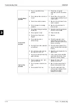
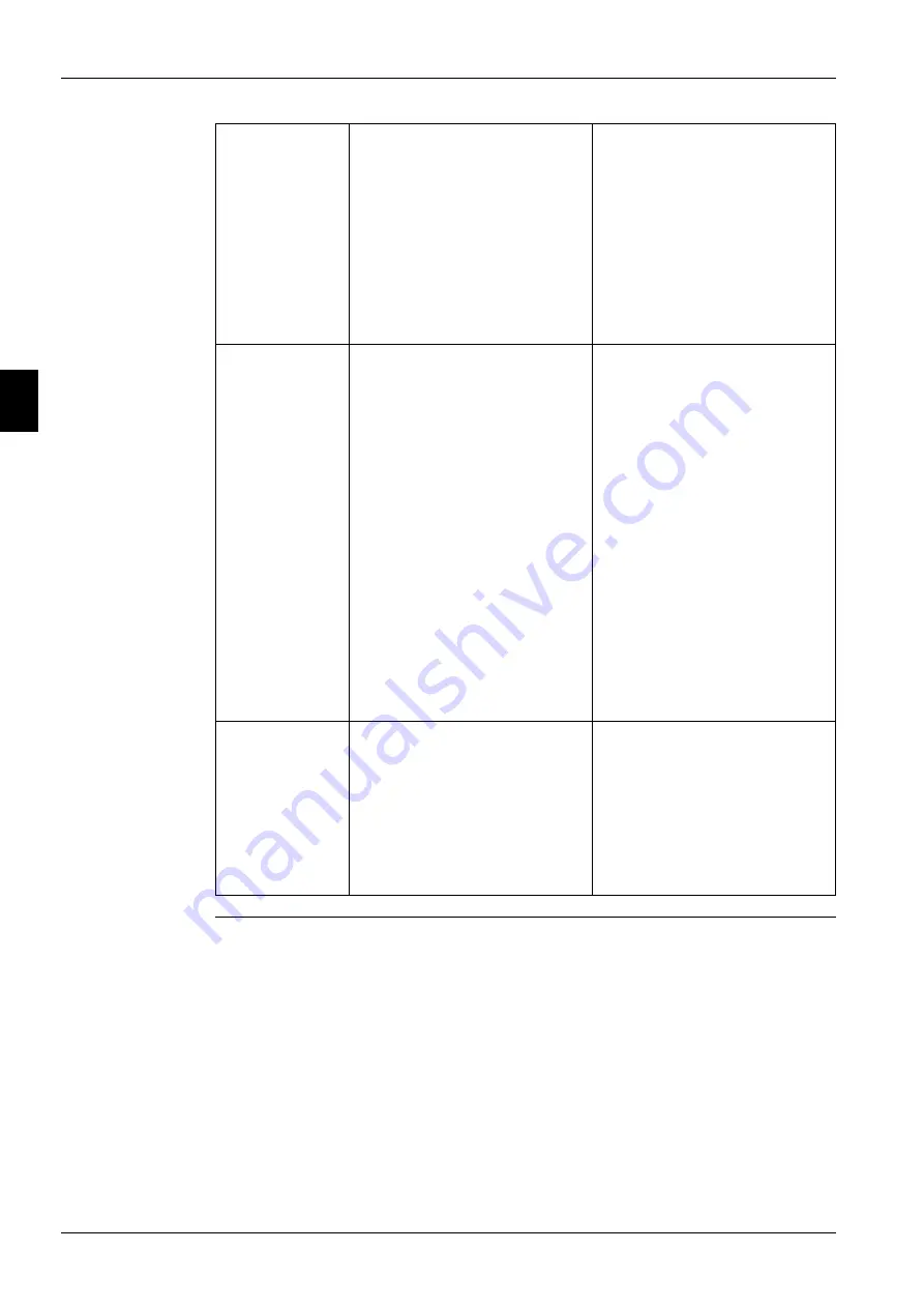
Low discharge
pressure
1
There is wind effect at low
ambient.
1
Protect the unit against
excessive wind into the vertical
coils.
2
The condenser fan control is not
correct.
2
Check if the unit set-up in the
microprocessor matches the unit
model number.
3
There is low suction pressure.
3
See the corrective steps for low
suction pressure.
4
The compressor is operating
unloaded.
4
See the corrective steps for
failure to load.
Low suction
pressure
1
The refrigerant charge quantity is
inadequate.
1
Check the liquid line sight-glass.
Check the unit for leaks.
2
The evaporator is dirty.
2
Clean chemically.
3
The liquid line filter-drier is
clogged.
3
Replace.
4
The expansion valve is
malfunctioning.
4
Check the expansion valve
superheat and valve opening
positions. Replace only the valve
that is not working.
5
The water flow to the evaporator
is insufficient.
5
Check the water pressure drop
across the evaporator and adjust
the flow.
6
The water temperature leaving
the evaporator is too low.
6
Adjust the water temperature to a
higher value.
7
There is an evaporator head ring
gasket slippage.
7
If the suction pressure
and
the
superheat are both low, it may
indicate an internal problem.
High suction
pressure
1
There is excessive load - high
water temperature.
1
Reduce the load or add
additional equipment.
2
The compressor unloaders are
open.
2
See corrective steps below for
failure of compressor to load.
3
The superheat is too low.
3
Check the superheat on the
microprocessor display. Check
the suction line sensor
installation and sensor.
Summary of Contents for EWAD620-C17C-SS
Page 2: ......
Page 8: ...ESIE10 01 1 2 Part 1 System Outline 3 1 1 5...
Page 111: ...ESIE10 01 General Outline Part 1 System Outline 1 105 3 1 4 5 1 36 1 Power Compressor 1 2...
Page 112: ...General Outline ESIE10 01 1 106 Part 1 System Outline 3 1 1 4 5 1 36 2 Power Compressor 3...
Page 113: ...ESIE10 01 General Outline Part 1 System Outline 1 107 3 1 4 5 1 36 3 Kit Pumps...
Page 122: ...General Outline ESIE10 01 1 116 Part 1 System Outline 3 1 1 4 5 1 36 12 Digital Inputs Board...
Page 123: ...ESIE10 01 General Outline Part 1 System Outline 1 117 3 1 4 5 1 36 13 Digital Outputs Board...
Page 124: ...General Outline ESIE10 01 1 118 Part 1 System Outline 3 1 1 4 5 1 36 14 Digital Outputs Board...
Page 127: ...ESIE10 01 General Outline Part 1 System Outline 1 121 3 1 4 5 1 36 17 Extension Control Fans 4...
Page 131: ...ESIE10 01 General Outline Part 1 System Outline 1 125 3 1 4 5 1 36 21 EEXV Compressor 1...
Page 134: ...General Outline ESIE10 01 1 128 Part 1 System Outline 3 1 1 4 5 1 36 24 EEXV Compressor 2...
Page 137: ...ESIE10 01 General Outline Part 1 System Outline 1 131 3 1 4 5 1 36 27 EEXV Compressor 3...
Page 138: ...General Outline ESIE10 01 1 132 Part 1 System Outline 3 1 1 4 5 1 36 28 Pumps Control...
Page 139: ...ESIE10 01 General Outline Part 1 System Outline 1 133 3 1 4 5 1 36 29 Terminals M1 M2...
Page 140: ...General Outline ESIE10 01 1 134 Part 1 System Outline 3 1 1 4 5 1 36 30 Terminals M3...
Page 141: ...ESIE10 01 General Outline Part 1 System Outline 1 135 3 1 4 5 1 36 31 Terminals M5 MQ...
Page 148: ...General Outline ESIE10 01 1 142 Part 1 System Outline 3 1 1 4 5...
Page 150: ...ESIE10 01 2 2 Part 2 Functional Description 3 1 2 5...
Page 170: ...The Digital Controller ESIE10 01 2 22 Part 2 Functional Description 3 1 2 4 5...
Page 200: ...Functional Control ESIE10 01 2 52 Part 2 Functional Description 3 1 2 4 5...
Page 202: ...ESIE10 01 3 2 Part 3 Troubleshooting 3 1 3 5...
Page 254: ...Alarms and Events ESIE10 01 3 54 Part 3 Troubleshooting 3 1 3 4 5...
Page 266: ...Controller Inputs and Outputs ESIE10 01 3 66 Part 3 Troubleshooting 3 1 3 4 5...
Page 280: ...ESIE10 01 4 2 Part 4 Commissioning and Test Run 3 1 4 5...
Page 286: ...Pre Test Run Checks ESIE10 01 4 8 Part 4 Commissioning and Test Run 3 1 4 5...
Page 289: ...ESIE10 01 Running Data Part 4 Commissioning and Test Run 4 11 3 4 5 1...
Page 290: ...Running Data ESIE10 01 4 12 Part 4 Commissioning and Test Run 3 1 4 5...


