Procedure to Protect Compressor in Case of Frozen Evaporator
ESIE10-01
3–72
3
1
3
4
5
4.2
Procedure to Protect Compressor in Case of Frozen Evaporator
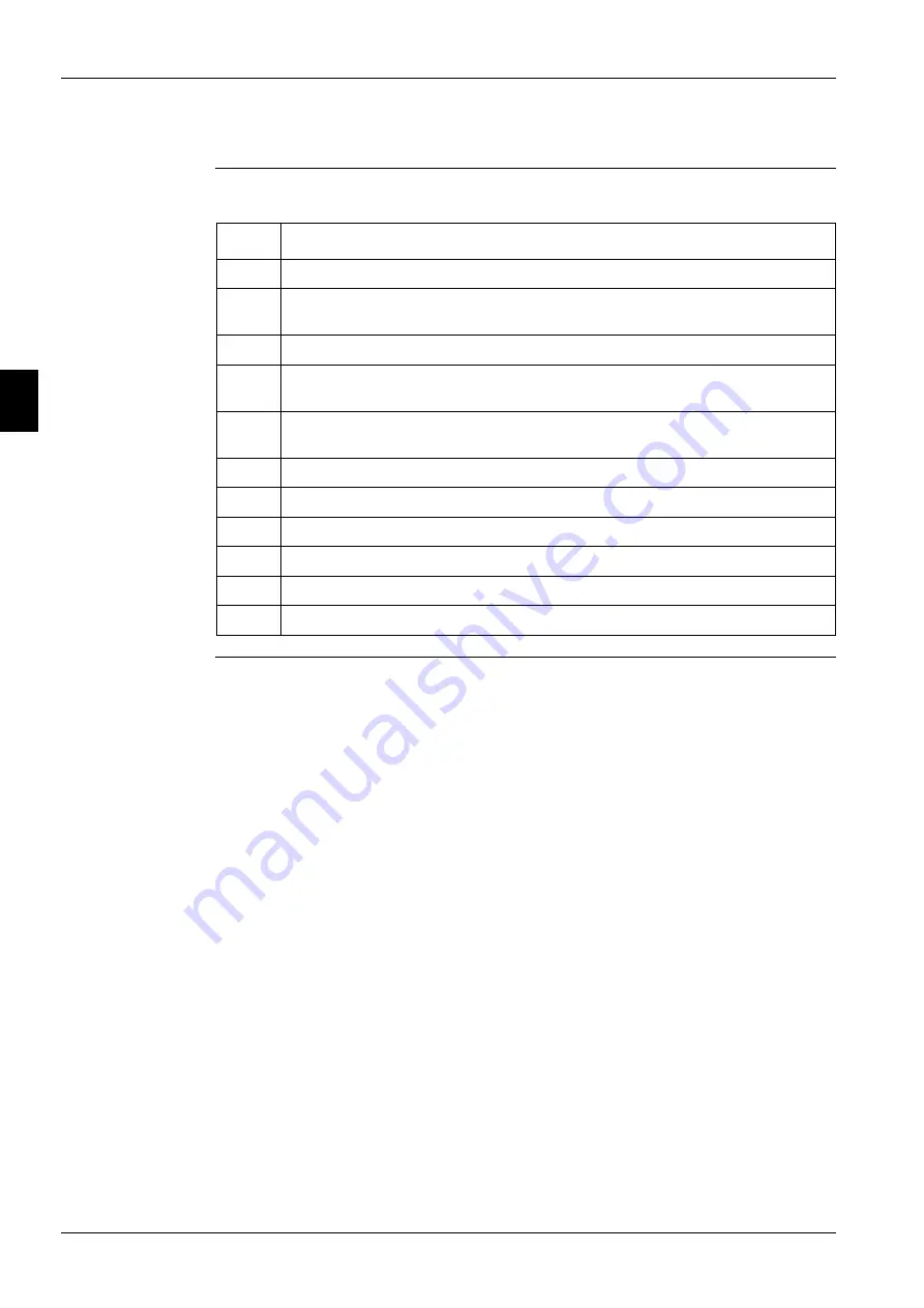
If water is detected in the compressor after an evaporator damage, the following procedure should be
executed within the first day.
Step
Action
1
Supply the compressor crank case heater.
2
Insulate the compressor from the rest of the refrigerant circuit. If there is no suction
valve available on the compressor, use a plate to close the suction of the compressor.
3
Open the oilplugs to drain the oil and the water out of the compressor.
4
Blow-dry nitrogen through the compressor using the service ports on the HP and LP
side of the compressor.
5
Close the drain plugs and vacuum the compressor for a few hours while the crank case
heater is on.
6
If the vacuum oil becomes coloured (milky colour) replace the vacuum oil.
7
Repeat step 6 each time the vacuum oil becomes milky.
8
After 4 hours break the vacuum using step 3.
9
Repeat step 5 till step 7 until the oil of the vacuum pump becomes clear.
10
If the vacuum oil remains clear fill the compressor with the necessary compressor oil.
11
Charge the compressor with nitrogen.
Summary of Contents for EWAD620-C17C-SS
Page 2: ......
Page 8: ...ESIE10 01 1 2 Part 1 System Outline 3 1 1 5...
Page 111: ...ESIE10 01 General Outline Part 1 System Outline 1 105 3 1 4 5 1 36 1 Power Compressor 1 2...
Page 112: ...General Outline ESIE10 01 1 106 Part 1 System Outline 3 1 1 4 5 1 36 2 Power Compressor 3...
Page 113: ...ESIE10 01 General Outline Part 1 System Outline 1 107 3 1 4 5 1 36 3 Kit Pumps...
Page 122: ...General Outline ESIE10 01 1 116 Part 1 System Outline 3 1 1 4 5 1 36 12 Digital Inputs Board...
Page 123: ...ESIE10 01 General Outline Part 1 System Outline 1 117 3 1 4 5 1 36 13 Digital Outputs Board...
Page 124: ...General Outline ESIE10 01 1 118 Part 1 System Outline 3 1 1 4 5 1 36 14 Digital Outputs Board...
Page 127: ...ESIE10 01 General Outline Part 1 System Outline 1 121 3 1 4 5 1 36 17 Extension Control Fans 4...
Page 131: ...ESIE10 01 General Outline Part 1 System Outline 1 125 3 1 4 5 1 36 21 EEXV Compressor 1...
Page 134: ...General Outline ESIE10 01 1 128 Part 1 System Outline 3 1 1 4 5 1 36 24 EEXV Compressor 2...
Page 137: ...ESIE10 01 General Outline Part 1 System Outline 1 131 3 1 4 5 1 36 27 EEXV Compressor 3...
Page 138: ...General Outline ESIE10 01 1 132 Part 1 System Outline 3 1 1 4 5 1 36 28 Pumps Control...
Page 139: ...ESIE10 01 General Outline Part 1 System Outline 1 133 3 1 4 5 1 36 29 Terminals M1 M2...
Page 140: ...General Outline ESIE10 01 1 134 Part 1 System Outline 3 1 1 4 5 1 36 30 Terminals M3...
Page 141: ...ESIE10 01 General Outline Part 1 System Outline 1 135 3 1 4 5 1 36 31 Terminals M5 MQ...
Page 148: ...General Outline ESIE10 01 1 142 Part 1 System Outline 3 1 1 4 5...
Page 150: ...ESIE10 01 2 2 Part 2 Functional Description 3 1 2 5...
Page 170: ...The Digital Controller ESIE10 01 2 22 Part 2 Functional Description 3 1 2 4 5...
Page 200: ...Functional Control ESIE10 01 2 52 Part 2 Functional Description 3 1 2 4 5...
Page 202: ...ESIE10 01 3 2 Part 3 Troubleshooting 3 1 3 5...
Page 254: ...Alarms and Events ESIE10 01 3 54 Part 3 Troubleshooting 3 1 3 4 5...
Page 266: ...Controller Inputs and Outputs ESIE10 01 3 66 Part 3 Troubleshooting 3 1 3 4 5...
Page 280: ...ESIE10 01 4 2 Part 4 Commissioning and Test Run 3 1 4 5...
Page 286: ...Pre Test Run Checks ESIE10 01 4 8 Part 4 Commissioning and Test Run 3 1 4 5...
Page 289: ...ESIE10 01 Running Data Part 4 Commissioning and Test Run 4 11 3 4 5 1...
Page 290: ...Running Data ESIE10 01 4 12 Part 4 Commissioning and Test Run 3 1 4 5...


