background image


EWAQ+EWYQ009~0 EWAQ+EWYQ009~013ACW1


Packaged air-cooled water chillers and packaged reversible air to 
water heatpumps


4PW51588-1


Operation manual


2


O


PERATING


THE


UNIT


O


PERATING


THE


DIGITAL


CONTROLLER


Operating the unit comes down to operating the digital controller.


Features and functions


The digital controller is a state of the art controller that offers full
control over your installation. It can control a cooling/heating and a
cooling only installation.

Both installations are available in multiple versions which vary in
capacity.


Basic controller functions


The basic controller functions are:


Turning the unit ON/OFF.


Operation mode change-over:
-

heating (refer to 

"Heating operation (


h


)" on page 4

),

-

cooling (refer to 

"Cooling operation (


c


)" on page 4

),

-

quiet mode (refer to 

"Quiet mode operation (


s


)" on page 4

),


Selection of features:
-

quiet mode (refer to 

"Quiet mode operation (


s


)" on page 4

),

-

weather dependent control (refer to 

"Selecting weather 

dependent set point operation (heat pump models only)" on 
page 4

).


Temperature set point adjustment (refer to 

"Controller

operations" on page 4

).

The digital controller supports a power cut off of maximum 2 hours.
When autorestart is enabled (see 

"Field settings" on page 9

) this

allows a power supply shut down of 2 hours without user intervention
(e.g. benefit kWh rate power supply).


Clock function


The clock functions are:


24 hour real time clock.


Day of the week indicator.


Schedule timer function


The schedule timer function allows the user to schedule the
operation of the installation according to a daily or a weekly program.


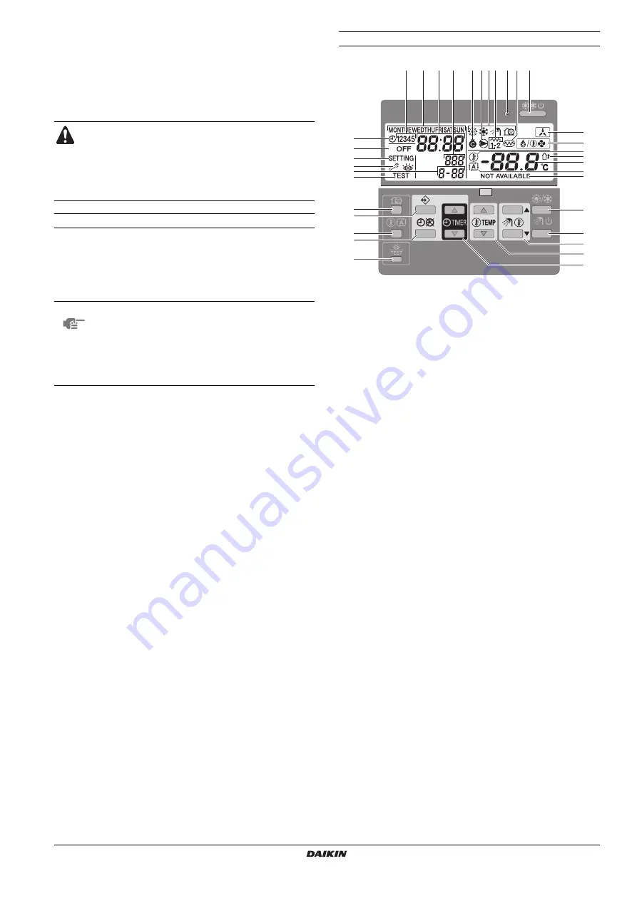
Name and function of buttons and icons


1.


COOLING/HEATING ON/OFF BUTTON 


y


The ON/OFF button starts or stops the heating or cooling
function of the unit.

When the unit is connected with an external room thermostat,
this button is not operable and the icon 


e


 is shown.

Pressing the ON/OFF button consecutively too many times may
cause malfunction of the system (maximum 20 times per hour).


2.


OPERATION LED 


0


The operation LED is lit during cooling or heating operation. The
LED blinks if a malfunction occurs. When the LED is OFF,
cooling or heating are inactive.


3.


OPERATION MODE ICONS 


hcs


These icons indicate the current operation mode(s): heating (


h


),

cooling (


c


) or quiet mode (


s


). Quiet mode is a feature of the

cooling or heating operation mode. When quiet mode is
activated, the quiet mode icon and the heating or cooling mode
icon will be displayed simultaneously.

In a heating only installation, the 


c


 icon will never be displayed.

In a cooling only installation, the 


h


 icon will never be displayed.


4.


EXTERNAL CONTROL ICON 


e


This icon indicates that an external room thermostat with higher
priority is controlling your installation. This external room
thermostat can start and stop the heating/cooling operation and
change the operation mode (cooling/heating).

When an external room thermostat with a higher priority is
connected, the schedule timer for cooling and heating will not
function.


5.


DAY OF THE WEEK INDICATOR 


1234567


This indicator shows the current weekday.

When reading or programming the schedule timer, the indicator
shows the set day.


6.


CLOCK DISPLAY 


8


The clock display shows the current time.

When reading or programming the schedule timer, the clock
display shows the action time.


7.


SCHEDULE TIMER ICON 


p


This icon indicates that the schedule timer is enabled.


8.


ACTION ICONS 


q


These icons indicate the programming actions for each day of
the schedule timer.


9.


OFF ICON 


x


This icon indicates that the OFF action is selected when
programming the schedule timer.


Never let the digital controller get wet. This may cause an
electric shock or fire.

Never press the buttons of the digital controller with a hard,
pointed object. This may damage the digital controller.

Never inspect or service the digital controller yourself, ask
a qualified service person to do this.


NOTE


Descriptions in this manual that apply to a specific
installation or that depend on the installed
equipment, are marked with an asterisk (*).


Some functions described in this manual may not
be available or should not be available. Ask your
installer or your local dealer for more information
on permission levels.

1

17

3

5

6

24

8

13

25

26

11

19

21

14

4

7

9

12
10

22

34

27

28

23

20

33

32

31

29

30

2

16

18

15

Summary of Contents for EWAQ009ACV3

Page 1: ...Q009ACV3 EWAQ010ACV3 EWAQ011ACV3 EWYQ009ACV3 EWYQ010ACV3 EWYQ011ACV3 EWAQ009ACW1 EWAQ011ACW1 EWAQ013ACW1 EWYQ009ACW1 EWYQ011ACW1 EWYQ013ACW1 Packaged air cooled water chillers and packaged reversible air to water heatpumps ...

Page 2: ...erter chiller THIS MANUAL This manual describes how to start up and switch off the unit set parameters and configure the schedule timer by means of the controller maintain the unit and solve operational problems THIS UNIT This unit is designed for outdoor installation and used for both heating and cooling applications The unit is designed to be combined with fan coil units or air handling units fo...

Page 3: ...eration The LED blinks if a malfunction occurs When the LED is OFF cooling or heating are inactive 3 OPERATION MODE ICONS hcs These icons indicate the current operation mode s heating h cooling c or quiet mode s Quiet mode is a feature of the cooling or heating operation mode When quiet mode is activated the quiet mode icon and the heating or cooling mode icon will be displayed simultaneously In a...

Page 4: ...This multi purpose button is used to program the controller The function of the button depends on the actual status of the controller or on previous actions carried out by the operator 30 SCHEDULE TIMER BUTTON r p The main function of this multi purpose button is to enable disable the schedule timer The button is also used to program the controller The function of the button depends on the actual ...

Page 5: ...utton The operation LED 0 lights up Selecting quiet mode operation s 1 Use the s button to activate quiet mode operation s Icon s appears on the display If the controller is set in permission level 2 or 3 refer to Field settings on page 9 the s button will not be operable Selecting weather dependent set point operation heat pump models only 1 Press the ba button to select weather dependent set poi...

Page 6: ... the actual setting one should consult the last programmed command It is clear that the last programmed command may date from the day before Refer to Consulting programmed actions on page 8 NOTE Only use the pr button to enable or disable the schedule timer The schedule timer overrules the y button The y button only overrules the schedule timer until the next programmed action If the auto restart ...

Page 7: ... setpoint heating actions are added automatically at the same time but with the default heating set point The set points of these automatically added actions can be adjusted by programming the corresponding mode This means that after programming heating you should also program the corresponding cooling set points and vice versa Programming Programming cooling or heating Due to the fact that the sc...

Page 8: ...y shows the highest action number you would like to save 12 Press the button for 5 seconds to store the programmed actions If the button is pressed when action number 3 is displayed actions 1 2 and 3 are stored but 4 and 5 are deleted You automatically return to step 6 By pressing the pr button several times you return to previous steps in this procedure and finally return to normal operation Prog...

Page 9: ...mmed actions of a specific day to the next day e g copy all programmed actions from 1 to 2 To copy programmed actions to the next day proceed as follows 1 Press the button The actual mode is blinking 2 Use the pi and pj buttons to select the mode you want to program The selected mode is blinking You can leave programming by pressing the pr button 3 Press the button to confirm the selected mode The...

Page 10: ... code is indicated 2 with the set value displayed to the right 1 2 Press the bgi button to select the appropriate field setting first code 3 Press the bgj button to select the appropriate field setting second code 4 Press the pfi button and pfj button to change the set value of the select field setting 5 Save the new value by pressing the pr button 6 Repeat step 2 through 4 to change other field s...

Page 11: ...9 00 Heating set point upper limit maximum leaving water temperature for heating operation 9 01 Heating set point lower limit minimum leaving water temperature for heating operation 9 02 Cooling set point upper limit maximum leaving water temperature for cooling operation 9 03 Cooling set point lower limit minimum leaving water temperature for cooling operation 9 04 Overshoot setting defines how m...

Page 12: ...electricity company that contact will close and the unit will go in forced off mode 2 E Unit information readout E 00 Readout of the software version example 23 E 01 Readout of the EEPROM version example 23 E 02 Readout of the unit model identification example 11 E 03 Readout of the liquid refrigerant temperature E 04 Readout of the inlet water temperature D 00 Compressor 0 default Forced off 1 Fo...

Page 13: ...lable 6 Not available 7 Not available 8 Not available 9 Cooling and heating set point ranges 00 Heating set point upper limit 55 37 55 1 C 01 Heating set point lower limit 15 15 37 1 C 02 Cooling set point upper limit 22 18 22 1 C 03 Cooling set point lower limit 5 5 18 1 C 04 Overshoot setting 2 1 4 1 C A Quiet mode 00 Quiet mode type 0 0 2 01 Parameter 01 3 C Alarm output logic of EKRP1HB 00 Not...

Page 14: ...ong time e g 1 hour too late or too early Check if the clock and the day of the week are set correctly correct if necessary DISPOSAL REQUIREMENTS Dismantling of the unit treatment of the refrigerant of oil and of other parts must be done in accordance with relevant local and national legislation Your product is marked with this symbol This means that electrical and electronic products shall not be...

Page 15: ......

Page 16: ...4PW51588 1 Copyright Daikin ...

Reviews: