EWAQ016~ EWYQ016~064BAW
Packaged air-cooled water chiller
4PW70082-1C – 2013.07
Installation and operation manual
14
Procedure
1
Open the switch box cover.
2
Using the appropriate cable, connect the power supply and
communication cable(s) to the appropriate terminals as shown
on the wiring diagram and according to the figure of chapter
"4.6.6. Routing" on page 14.
3
Fix the cables with cable ties to the cable tie mountings to
ensure strain relief and to make sure that it does not come in
contact with the piping and sharp edges. Never squeeze
bundled cables.
Note: only relevant field wiring is shown in the figure of chapter
"4.6.6. Routing" on page 14.
4
Close the switch box cover following the instructions described
in "4.2.2. Opening the unit" on page 7 in reverse order.
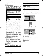
4.6.6.
Routing
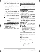
It is important to keep the power supply and the low voltage wiring
separated from each other. In order to avoid any electrical
interference the distance between both wirings should always be at
least 25 mm.
The wiring should be mounted as shown in figure 11.
PS = Power supply
LV = Low voltage
HV = High voltage
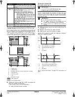
4.6.7.
Installation of the remote controller
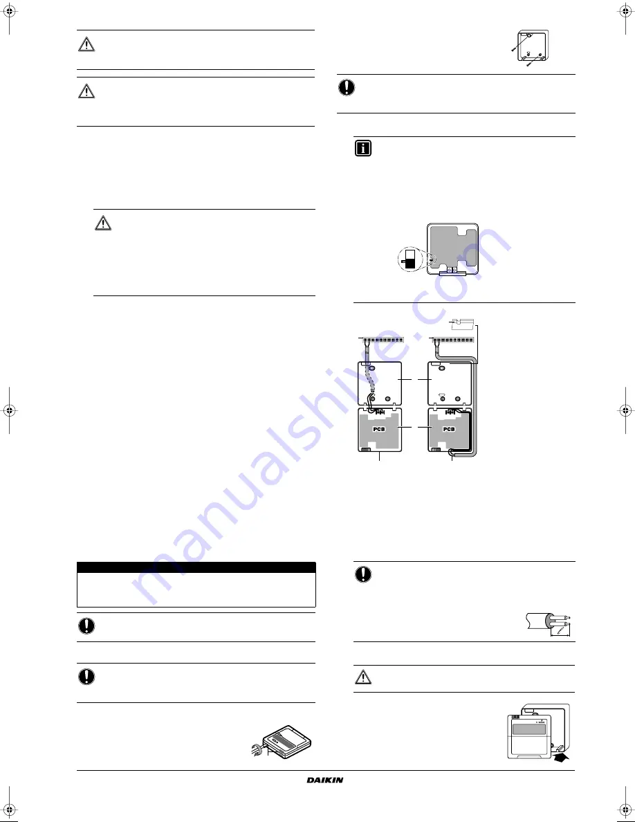
The unit is equipped with a remote controller offering a user-friendly
way to set up, use and maintain the unit. Before operating the
controller, follow this installation procedure.
Wiring specifications
Procedure
1
Remove the front part of the remote controller.
Insert a slotted screwdriver into the slots (1)
in the rear part of the remote controller, and
remove the front part of the remote
controller.
2
Fasten the remote controller on a flat
surface.
3
Wire the unit.
1
Unit
2
Rear part of the remote controller
3
Front part of the remote controller
4
Wired from the rear
5
Wired from the top
6
Use nippers to notch the part for the wiring to pass through
Connect the terminals of the remote controller and the terminals
inside the unit (P1 to P1, P2 to P2) as shown in the figure above.
4
Reattach the upper part of the remote controller.
First begin fitting from the clips at the
bottom.
CAUTION
Select all cables and wire sizes in accordance with
relevant local and national regulations.
WARNING
After finishing the electric work, confirm that each electric
part and terminal inside the electric parts box is connected
securely.
■
To avoid receiving electric noise, be sure that the
cables are put in the correct bundle and routed in
the correct bundle tray as shown in the figure of
chapter "4.6.6. Routing" on page 14.
■
When wiring, route the cable bundles that are
outside the unit away from each other by at least
25 mm in order to avoid receiving electric noise
(external noise).
Wire specification
Value
Type
2 wire
Section
0.75~1.25 mm
2
Maximum length
500 m
NOTICE
The wiring for connection is not included.
NOTICE
The remote controller, delivered in a kit, has to be mounted
indoors.
1
NOTICE
Be careful not to distort the shape of the lower part of the
remote controller by over tightening the mounting screws.
INFORMATION
If next to the standard remote controller the optional
remote controller is installed as well:
■
Connect the electrical wires of both remote
controllers in the same way like described below.
■
Select a master and a slave remote controller by
switching the SS1 selector switch.
Only the remote controller set as master can work as
room thermostat.
NOTICE
■
When wiring, run the wiring away from the power
supply wiring in order to avoid receiving electric
noise (external noise).
■
Peel the shield for the part that
has to pass through the inside of
the remote controller case (
l
).
CAUTION
Be careful not to pinch the wiring when attaching.
S
S
M
PCB
SS1
S
Slave
M
Master
P1
P2
1
1
6
2
3
4
5
P1
P2
P2
P1
P2
P1
1
4PWEN70082-1C.book Page 14 Wednesday, September 25, 2013 7:31 AM
Summary of Contents for EWAQ016BAW
Page 47: ......


