background image

EWAQ016~ EWYQ016~064BAW

Packaged air-cooled water chiller

4PW70082-1C – 2013.07

Installation and operation manual

20

[3] Weather dependent set point

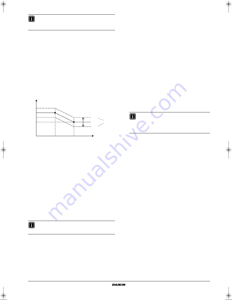
When weather dependent operation is active, the leaving water
temperature is determined automatically depending on the outdoor
temperature: colder outdoor temperatures will result in warmer water
and vice versa. The unit has a floating set point. Activating this
operation will result in a lower power consumption than use with a
manually fixed leaving water set point.

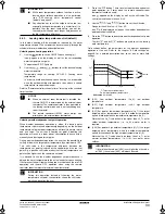
During weather dependent operation, the user has the possibility to
shift up or down the target water temperature by a maximum of 5°C.
This "Shift 

value" is the temperature difference between the

temperature set point calculated by the controller and the real set
point. E.g. a positive shift value means that the real temperature set
point will be higher than the calculated set point.

It is advised to use the weather dependent set point because it
adjusts the water temperature to the actual needs for space heating.
It will prevent the unit from switching too much between thermo ON
operation and thermo OFF operation when using the remote
controller room thermostat or external room thermostat.

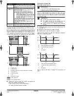
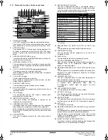
[3-00]

  Low ambient temperature (Lo_A): low outdoor

temperature.

[3-01]

  High ambient temperature (Hi_A): high outdoor

temperature.

[3-02]

  Set point at low ambient temperature (Lo_Ti): the target

outgoing water temperature when the outdoor temperature
equals or drops below the low ambient temperature (Lo_A).
Note that the Lo_Ti value should be higher than Hi_Ti, as for
colder outdoor temperatures (i.e. Lo_A) warmer water is
required.

[3-03]

 Set point at high ambient temperature (Hi_Ti): the target

outgoing water temperature when the outdoor temperature
equals or rises above the high ambient temperature (Hi_A).
Note that the Hi_Ti value should be lower than Lo_Ti, as for
warmer outdoor temperatures (i.e. Hi_A) less warm water
suffices.

[4] Settings are not applicable

[5] Automatic setback

[5-00]

 Setting is not applicable.

[5-01]

 Setting is not applicable.

[5-02]

 Leaving water setback temperature.

[5-03]

 Room temperature setback.

[5-04]

 Setting is not applicable.

[6] Option setup

[6-01]

 External room thermostat option

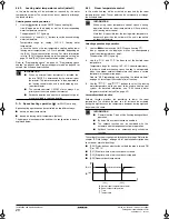
If the optional external room thermostat is installed, its operation
must be enabled by field setting. Default [6-01]=0, which means
no external room thermostat is installed. Set [6-01] to 1 or 2 if
the optional external room thermostat is installed.
The external room thermostat only gives an ON/OFF signal to
the heat pump based on the room temperature. Because it does
not give continuous feedback information to the heat pump, it is
supplementary to the remote controller room thermostat
function. To have a good control of the system and avoiding
frequent ON/OFF it is advised to use the automatic weather
dependent set point operation.

[6-01]

=1

Room thermostat input 1 = heating operation ON (1)/OFF (0)
Room thermostat input 2 = cooling operation ON (1)/OFF (0)

[6-01]

=2 

Room thermostat input 1 = operation ON (1)/OFF (0)
Room thermostat input 2 = cooling (1)/heating (0) selection

[6-03]

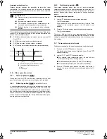
 Negative leaving water temperature setting

This setting is only applicable for units with a low temperature
cooling option below 0°C ([A-04]=1).
It is not possible to set negative leaving water temperature
settings directly on the remote controller. This has to be done
through this setting.
Example: [6-03]=–5 sets negative leaving water temperature set
point to –5°C.

[7] Option setup

[7-00]

 Forced pump operation

[7-00]

=0 the pump performs intermittent sampling during

thermo off conditions. This setting is often used when the unit
is controlled by a room thermostat.

[7-00]

=1 the pump continues operation during thermo off

conditions (default)

[8] Option setup

[8-00]

 Remote controller temperature control

[8-00]

=0 the unit operates in leaving water temperature

control. This is the default setting.

[8-00]

=1 the unit operates in room temperature control. This

means that the remote controller is used as room thermostat,
so the remote controller can be placed in the living room to
control the room temperature.

[8-01]

 Setting is not applicable

[8-03]

 Setting is not applicable.

INFORMATION

Only for EWYQ units operating in heating mode.

Setback function for cooling does not exist.

T

t

Target water temperature

T

A

Ambient (outdoor) temperature

Shift value

= Shift value

INFORMATION

If by mistake the value of [3-03] is set higher than the value
of [3-02], the value of [3-03] will always be used.

Lo_Ti

Lo_A

Hi_A

T

A

T

t

+ 05

00

– 05

Hi_Ti

Shift value

INFORMATION

The unit will only accept this negative leaving water
set point when leaving water set point on the remote
controller display is set to 0°C (after changing [C-03]
to 0) and the field setting [A-04]=1.

4PWEN70082-1C.book  Page 20  Wednesday, September 25, 2013  7:31 AM

Summary of Contents for EWAQ016BAW

Page 1: ...N AND OPERATION MANUAL EWAQ016BAW EWAQ021BAW EWAQ025BAW EWAQ032BAW EWAQ040BAW EWAQ050BAW EWAQ064BAW EWYQ016BAW EWYQ021BAW EWYQ025BAW EWYQ032BAW EWYQ040BAW EWYQ050BAW EWYQ064BAW Packaged air cooled wat...

Page 2: ...0 7 N m 6 ON OFF A N 1 1 2 2 ON I OFF O 016 025 032 040 050 064 1684 1684 1684 1684 1340 1650 2320 2940 775 775 780 780 EWAQ EWYQ H mm W mm D mm 729 765 765 631 A B 729 765 765 631 A B C B 1 2 3 4 5 6...

Page 3: ...50 200 250 300 1 1 2 2 3 3 4 4 EWA YQ016 025BAWN 1 EWA YQ032BAWN 2 EWA YQ040 050BAWN 3 EWA YQ064BAWN 4 140 160 180 200 120 100 80 60 40 20 0 0 50 100 150 200 250 300 1 1 2 2 3 3 4 4 43 5 15 0 10 0 5 2...

Page 4: ...e cu Certificatul C conform celor stabilite n Dosarul tehnic de construc ie D i apreciate pozitiv de E Modul aplicat F n conformitate cu Certificatul G Categorie de risc H Consulta i de asemenea pagin...

Page 5: ...a kyll stysl mp tila M C Kylm aine N Varmuuspainelaitteen asetus P bar Valmistusnumero ja valmistusvuosi katso mallin nimikilpi 14 Maxim ln p pustn tlak PS K bar Minim ln maxim ln p pustn teplota TS T...

Page 6: ...3 2 Unit test run 22 5 4 Handover to the user 22 5 5 Service and maintenance 23 5 5 1 Maintenance activities 23 5 5 2 Error codes 23 5 5 3 Important information regarding the refrigerant used 23 6 Uni...

Page 7: ...livered with the unit Contact your local dealer for an electronic version of the manual For detailed instructions about how to install and operate the associated products and or optional equipment ref...

Page 8: ...n the working condition of the unit Your hand may get burned or frostbitten if you touch the piping or internal parts To avoid injury give the piping and internal parts time to return to normal temper...

Page 9: ...e the air contains high levels of salt such as that near the ocean 3 2 3 Selecting a location in cold climates To prevent exposure to wind and snow install a baffle plate on the air side of the outdoo...

Page 10: ...ble legislation Failure to do so may cause electric shock or fire Be sure to use a dedicated power circuit never use a power supply shared by another appliance When installing the earth leakage protec...

Page 11: ...the unit when removing the shrink foil with a cutter Remove the top palette s and cardboard plate s before removing the upright cardboard protection pieces Refer to figure 3 Remove the screws fixing...

Page 12: ...how to get access to the accessories Refer to the table below for reference to where following accessories are supplied with the unit NOTICE Prepare a water drainage channel around the foundation to...

Page 13: ...4 4 2 Main components of the hydro module Hydraulic compartment panel 3 1 Air purge valve Remaining air in the water circuit will be automatically removed via the air purge valve Refer to E 04 Pump on...

Page 14: ...rature sensors A Water side B Refrigerant side C Water outlet field installation D Water inlet field installation E Only for P models F Refrigerant flow in cooling mode G Refrigerant flow in heating m...

Page 15: ...ion vessel pre pressure The unit is equipped with an expansion vessel of 12 litre which has a default pre pressure of 1 bar To assure proper operation of the unit the pre pressure of the expansion ves...

Page 16: ...tion on page 21 Depending on the expected lowest outdoor temperature make sure the water system is filled with a weight concentration of glycol as mentioned in the table below Caution Use of glycol Al...

Page 17: ...e icer 2 sub cool H E gas 2 liquid 2 H E liquid 2 R10 Resistor current sensor R31T R32T Thermistor discharge M1C M2C R50 R59 Resistor R90 Resistor current sensor R95 Resistor current limiting S1NPH Pr...

Page 18: ...out of power supply always including earth and communication transmission wiring Most field wiring on the unit is to be made on the terminal blocks inside the switch boxes To gain access to the termi...

Page 19: ...e top 6 Use nippers to notch the part for the wiring to pass through Connect the terminals of the remote controller and the terminals inside the unit P1 to P1 P2 to P2 as shown in the figure above 4 R...

Page 20: ...ply voltage on the local supply panel The voltage must correspond to the voltage on the identification label of the unit 10 Air purge valve Make sure the air purge valve of the unit is open at least 2...

Page 21: ...eld setting BS3 RETURN For field setting BS4 TEST This push button has no function BS5 RESET This push button has no function LED display Default status before delivery Micro computer operation monito...

Page 22: ...of each field setting is given under 5 2 5 Detailed description on page 18 5 2 4 Procedure To change one or more field settings proceed as follows 1 Press the button for a minimum of 5 seconds to ent...

Page 23: ...programmed in 2 different ways based on the temperature set point both leaving water temperature and room temperature and based on the ON OFF instruction In the following tables both methods on how t...

Page 24: ...in active until the next programmed command occurs Example imagine the actual time is 17 30 and actions are programmed at 13 00 16 00 and 19 00 The last programmed command 16 00 overruled the previous...

Page 25: ...t is installed its operation must be enabled by field setting Default 6 01 0 which means no external room thermostat is installed Set 6 01 to 1 or 2 if the optional external room thermostat is install...

Page 26: ...operation 9 04 Setting not applicable A Option setup A 00 Setting is not applicable A 01 Setting is not applicable A 02 Setting is not applicable A 03 Leaving water temperature overshoot undershoot v...

Page 27: ...sh the button to start the test run operation 5 The test run operation will end automatically after 30 minutes or when reaching the set temperature The test run operation can be stopped manually by pr...

Page 28: ...tion on page 3 WARNING ELECTRIC SHOCK Before carrying out any maintenance or repair activity always switch off the circuit breaker on the supply panel remove the fuses or open the protection devices o...

Page 29: ...water condenser temperature EWC Entering water condenser temperature A Optional water glycol operation range B Standard water operation range C Pull down area D Pull up area E Protect the system agai...

Page 30: ...products as per the subject of this manual Field supply Equipment which needs to be installed according to instructions in this manual but which are not supplied by Daikin 2 GENERAL SAFETY PRECAUTIONS...

Page 31: ...ervention 5 1 3 Clock function The clock functions are 24 hour real time clock Day of the week indicator 5 1 4 Schedule timer function The schedule timer function allows the user to schedule the opera...

Page 32: ...a slave remote controller is used see installation manual 14 DEFROST START UP MODE ICON for EWYQ units only This icon indicates that the defrost start up mode is active 15 COMPRESSOR ICON This icon i...

Page 33: ...for 5 seconds The clock read out and the day of week indicator start flashing 2 Use the and buttons to adjust the clock Each time the or button is pressed the time will increase decrease by 1 minute...

Page 34: ...not operable when the outdoor ambient temperature rises above a certain temperature see operation range Refer to 5 9 Programming and consulting the schedule timer on page 33 for setup of the schedule...

Page 35: ...he shift value The shift value is not shown in case it is 0 2 Use the and buttons to set the shift value Range for the shift value 5 C to 5 C Icon will be displayed as long as the weather dependent se...

Page 36: ...possible 5 6 3 Quiet mode operation Quiet mode operation means that the unit works at reduced compressor speed so that the noise produced by the unit drops This implies that it will take longer till...

Page 37: ...e cooling based on temperature set point method 1 is enabled so only temperature shifts are possible no ON OFF instruction INFORMATION By default space heating based on temperature set point method 1...

Page 38: ...l way start with action 1 for the first action and end with the highest number for the last action This is not a requirement but will simplify the interpretation of the program later If 2 or more acti...

Page 39: ...t action time 8 Use the and buttons to set the leaving water temperature 9 Use the and buttons to set the room temperature 10 Use the button to select to switch cooling and the remote controller off 1...

Page 40: ...erature 10 Use the and buttons to set the room temperature 11 Use the button to select to switch heating and the remote controller off to select automatic temperature calculation for leaving water tem...

Page 41: ...mode The actual day is blinking 4 Select the day you would like to consult by means of the and buttons The selected day is blinking 5 Press the button to confirm the selected day The first programmed...

Page 42: ...day is blinking 5 Press the and button simultaneously for 5 seconds to delete the selected day 5 10 Operating the optional demand PCB An optional PCB EKRP1AHTA can be connected to the unit and be use...

Page 43: ...3 Press the button to select the appropriate field setting second code 4 Press the button and button to change the set value of the select field setting 5 Save the new value by pressing the button 6...

Page 44: ...10 20 1 C 02 Set point at low ambient temperature Lo_Ti 40 25 80 1 C 03 Set point at high ambient temperature Hi_Ti 25 25 80 1 C 4 Settings are not applicable 00 Not applicable Do not change the defa...

Page 45: ...cooling leaving water minimum temperature 5 Q a 18 1 C 04 Not applicable Do not change the default value 0 d Settings are not applicable 00 Not applicable Do not change the default value 10 01 Not ap...

Page 46: ...emote controller blank display Check if the mains power is still connected to your installation The benefit kWh rate power supply is active see installation manual One of the error codes appears Consu...

Page 47: ......

Page 48: ...4PW70082 1C 2013 07 Copyright 2011 Daikin...

Reviews: