D-EIMWC00208-16EN - 15/48
Determining Equivalent Line Length
To determine the appropriate size for field installed liquid and discharge lines, it is first necessary to establish the
equivalent length of pipe for each line. The equivalent length is the actual friction loss from the linear run of pipe plus t he
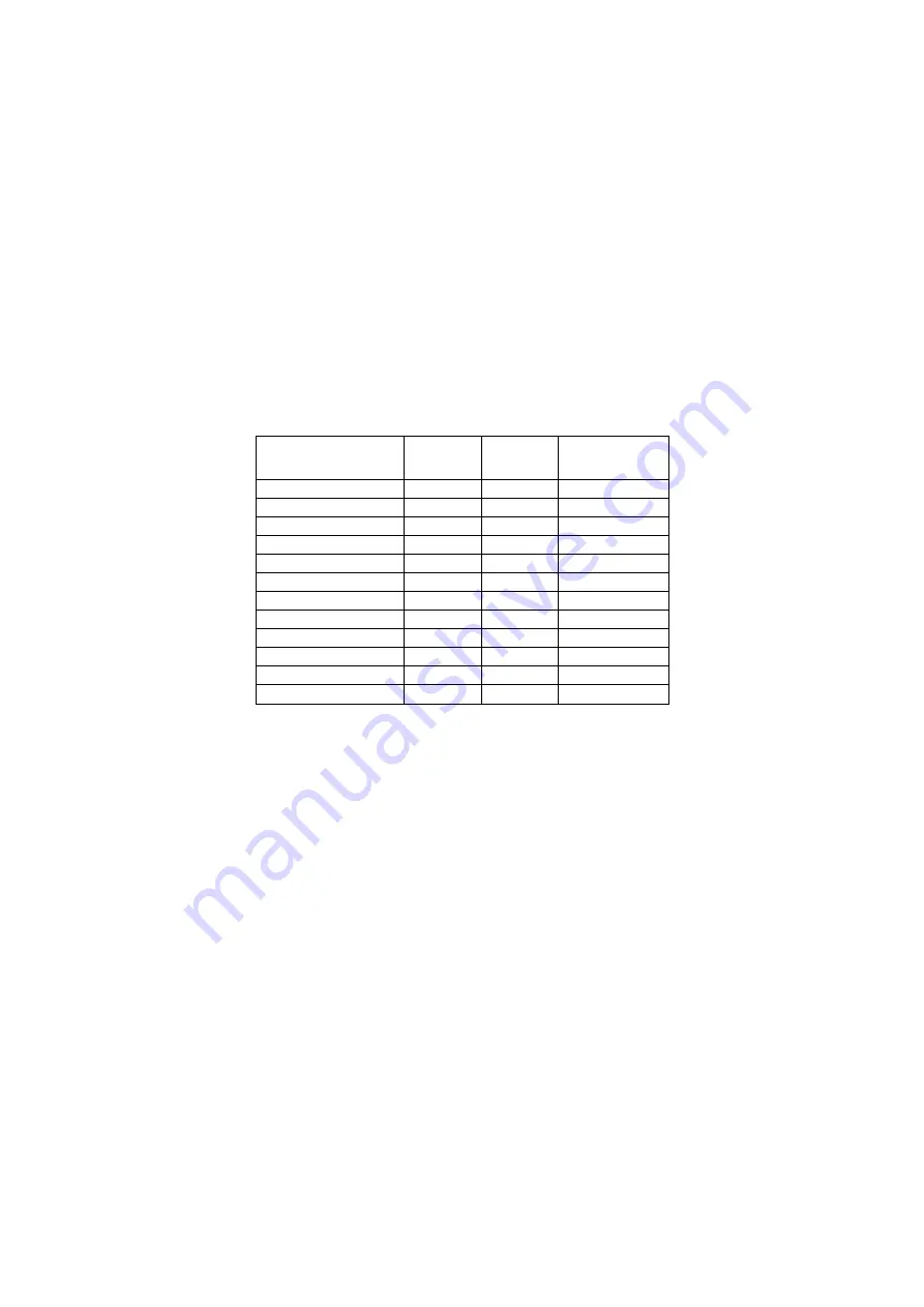
added friction loss of elbows, valves, etc. Table 2 shows the equivalent length of pipe for various nonferrous valves and
fittings. Follow these steps when calculating line size:
1.
Start with an initial approximation of equivalent length by assuming that the equivalent length of pipe i s 1.5 times
the actual pipe length.
2.
Refer to Tables 2 and 3 for a first approximation of line size.
3.
Check the line size by calculating the actual equivalent length.
Note: W hen calculating the equivalent length, do not include piping of the chille r unit. Only field piping must be
considered.
Table 2 - Equivalent Lengths (in meters)
Line Size
OD
(inches)
Angle
Valve
Short
Radius EL
Long
1/4
5.8
0.8
0.6
3/8
7.3
1.2
0.9
1/2
7.3
1.4
1.0
5/8
7.6
1.7
1.2
3/4
7.6
2.0
1.4
7/8
8.5
2.4
1.6
11/8
8.8
0.8
0.6
13/8
10.1
1.0
0.7
15/8
10.4
1.2
0.8
21/8
11.9
1.6
1.0
25/8
13.4
2.0
1.3
31/8
14.3
2.4
1.6
Liquid Line Sizing
In designing liquid lines it is important that the liquid reaches the expansion valve without flash gas, since this gas will
reduce the valve capacity. Because flashing gas can be caused by pressure drop in the line, the pressure losses due to
friction and changes in static head should be kept at minimum.
A check valve must be installed in the liquid line where the ambient temperature can drop below the equipment room
temperature to prevent liquid migration to the condenser and to maintain liquid refrigerant in the line for unit startup (if
thermostatic expansion valve is used, the check valve also help to keep liquid pressure high e nough to keep the valve
closed with compressor off).
A relief valve should be installed between the check valve and the expansion avlve.
The liquid line diameter should be as small as possible while maintaining acceptable pressure drop. This is necessary to
minimize refrigerant charge. The total length between the chiller unit and the aircooled condenser must not exceed 60
equivalent meters.
Liquid line risers in the system will require an additional 11.5 kPa pressure drop per meter of vertical rise. W hen it is
necessary to have a liquid line riser, make the vertical run immediately after the condenser before any additional
restrictions. The liquid line risers must not exceed 3 meters in height from the condenser liquid line connection. The liquid
line does not have to be pitched.
Liquid lines are not typically insulated. However, if the lines are exposed to solar heat gain or temperatures exceeding
43°C, subcooling may be effected. In these situations, insulate the liquid lines.
Reference for liquid line sizing is shown in Table 3. It has to be used for reference only, for circuit working with
condensing temperature equal to 55°C and 5°C subcooling at the condenser outlet. Line dimensioning is responsibility of
plant designer, use ASHRAE Refrigeration Handbook or other suitable design guide.
Summary of Contents for EWLD160~550G-SS
Page 21: ...D EIMWC00208 16EN 21 48 Fig 10 Refrigeration cycle EWWD G SS EWWD G XS 23 5 bar...
Page 23: ...D EIMWC00208 16EN 23 48 Fig 12 Refrigeration cycle EWLD G SS OPTIONAL 23 5 bar...
Page 45: ...D EIMWC00208 16EN 45 48...
Page 46: ...D EIMWC00208 16EN 46 48...
Page 47: ...D EIMWC00208 16EN 47 48...


