background image

Installation manual

6

EWLP012~065KBW1N

Condenserless water-cooled water chillers

4PW61665-1 – 07.2010

W

ATER


CHARGE

FLOW


AND


QUALITY

To  assure proper operation of the unit a minimum water volume is
required in the system and the water flow through the evaporator
must be within the operation range as specified in the table below.

W

ATER


PIPING


INSULATION

The complete water circuit, inclusive all piping, must be insulated to
prevent condensation and reduction of the cooling capacity.

Protect the water piping against water freezing during winter period
(e.g. by using a glycol solution or heatertape).

R

EFRIGERANT


PIPING


INSULATION

To  prevent burning injuries by accidental touching the hot (max
135°C) discharge pipe, it must be insulated thoroughly. 

A minimum of insulation to protect the liquid pipe from damage is
advisable.

I

NSTALLATION


OF


THE


CONDENSER


INLET


TEMPERATURE


SENSOR

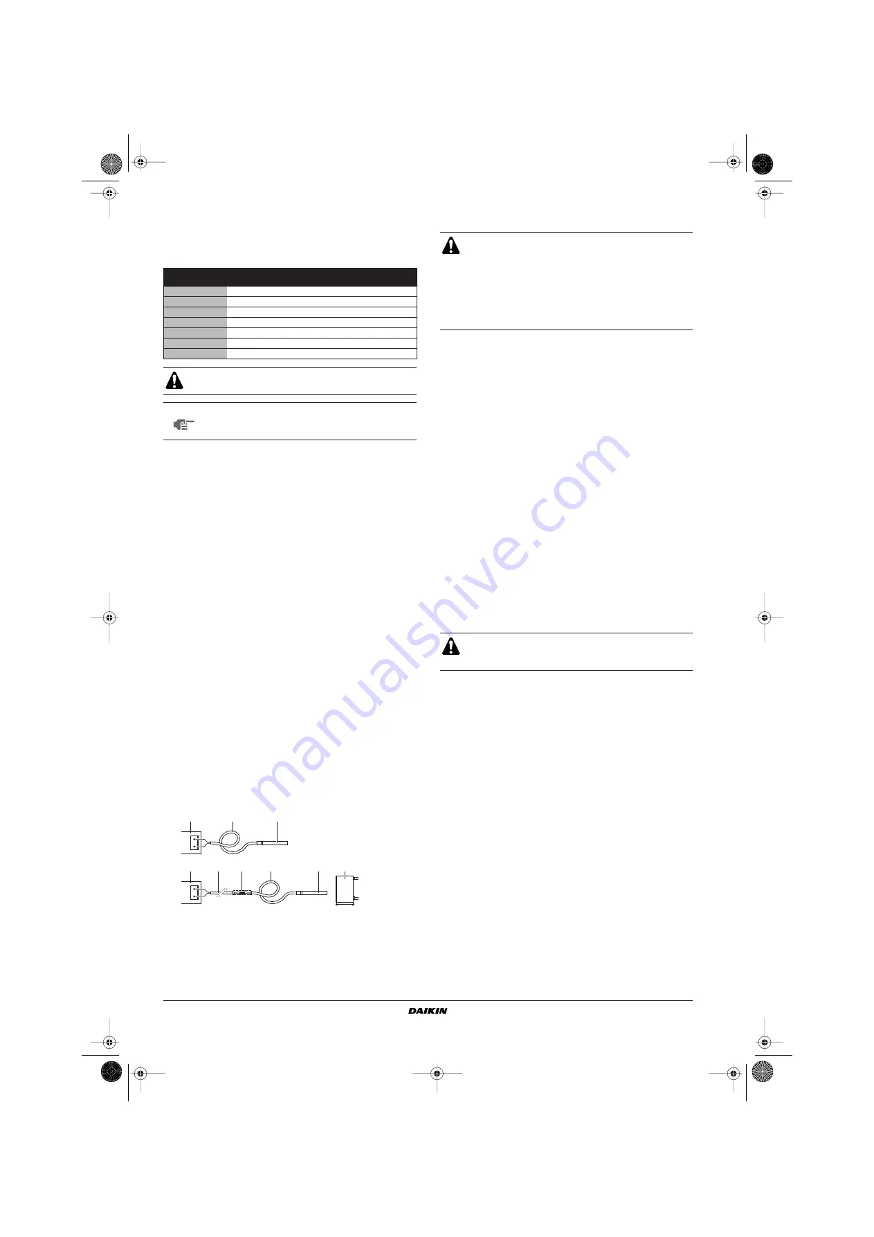
For condenser water inlet control it is possible to enlarge the provided
water sensor cable for a total length of 100 m. It gives the opportunity
to place the water sensor near to the remote watercooled condenser
in order to have a reliable condenser water inlet measurment.

Connecting sensors and power supply

Sensors can be located up to 100 meters distance away from the
controller provided that you use cables with Ø1 mm

2

  min. To improve

immunity against noises we recommend using shielded cables (connect
just one end of the shielding to the earth of the electrical panel).

F

IELD


WIRING


Parts table

F1,2,3 .................... Main fuses for the unit

H3P........................ Indication lamp alarm

H4P,H5P ................ Indication lamp operation compressor circuit 1, 

circuit 2

K1F,K2F ................. fancontactor

PE.......................... Main earth terminal

S7S........................ Switch for remote cooling/heating change-over 

valve or dual setpoint

S9S........................ Switch for remote start/stop or dual setpoint

- - - ......................... Field wiring

Power circuit and cable requirements

1

The electrical power supply to the unit must be arranged so that
it can be switched on or off independently of the electrical supply
to other items of the plant and equipment in general.

2

A power circuit must be provided for connection of the unit. This
circuit must be protected with the required safety devices, i.e. a
circuit breaker, a slow blow fuse on each phase and an earth
leak detector. Recommended fuses are mentioned on the wiring
diagram supplied with the unit. 

Connection of the water-cooled water chiller power 
supply

1

Using the appropriate cable, connect the power circuit to the N,
L1, L2 and L3 terminals of the unit. (cable section 2.5~10 mm

2

)

2

Connect the earth conductor (yellow/green) to the earthing
terminal PE.

Minimum 

water volume (l)

Minimum 

water flow

Maximum 

water flow

EWLP012

62.1

17 l/min

69 l/min

EWLP020

103

29 l/min

115 l/min

EWLP026

134

38 l/min

153 l/min

EWLP030

155

45 l/min

179 l/min

EWLP040

205

57 l/min

229 l/min

EWLP055

268

77 l/min

307 l/min

EWLP065

311

89 l/min

359 l/min

The water pressure should not exceed the maximum
working pressure of 10 bar.

NOTE

Provide adequate safeguards in the water circuit to
make sure that the water pressure will never exceed
the maximum allowable working pressure.

1

Switch box (with connector X62A on I/O PCB)

2

Sensor cable (length ±1 m)

3

Sensor

4

Remote watercooled condenser

5

Cable

6

Interconnection (IP67)

1

2

3

X62A

X62A

1

3

2

6

5

4

All field wiring and components must be installed by a
licensed electrician and must comply with relevant
European and national regulations.

The field wiring must be carried out in accordance with the
wiring diagram supplied with the unit and the instructions
given below.

Be sure to use a dedicated power circuit. Never use a
power supply shared by another appliance.

Switch off the main isolator switch before making any
connections (switch off the circuit breaker, remove or
switch off the fuses).

4PW61665-1_digital_EN.book  Page 6  Friday, August 27, 2010  2:13 PM

Summary of Contents for EWLP-KBW1N

Page 1: ...ATION MANUAL EWLP012KBW1N EWLP020KBW1N EWLP026KBW1N EWLP030KBW1N EWLP040KBW1N EWLP055KBW1N EWLP065KBW1N Condenserless water cooled water chillers 4PW61665 1_digital_EN book Page 1 Friday August 27 2010 2 13 PM ...

Page 2: ...ivo de B de acordo com o Certificado C 09 Примечание как указано в A и в соответствии с положительным решением B согласно Свидетельству C 10 Bemærk som anført i A og positivt vurderet af B i henhold til Certifikat C 11 Information enligt A och godkänts av B enligt Certifikatet C 12 Merk som det fremkommer i A og gjennom positiv bedømmelse av B ifølge Sertifikat C 13 Huom jotka on esitetty asiakirj...

Page 3: ...EWLP units Technical specifications 1 Electrical specifications 1 Options and features 1 Options Glycol application for chilled water temperature down to 10 C or 5 C BMS connection MODBUS optional kit address card EKAC10C 2 Remote user interface optional kit EKRUMCA Necessary to additionally install kit address card EKAC10C 2 Low noise operation kit field installation EWLP012KBW1N EWLP040KBW1N EWL...

Page 4: ...out of the unit The equipment is not intended for use in a potentially explosive atmosphere INSPECTING AND HANDLING THE UNIT At delivery the unit should be checked and any damage should be reported immediately to the carrier claims agent UNPACKING AND PLACING THE UNIT 1 Cut the straps and remove the cardboard box from the unit 2 Cut the straps and remove the cardboard boxes with waterpiping from t...

Page 5: ...d to prevent foreign materials e g mineral oils such as SUNISO and moisture from mixing into the system Vacuum pump use a 2 stage vacuum pump with a non return valve Make sure the pump oil does not flow oppositely into the system while the pump is not working Use a vacuum pump which can evacuate to 100 7 kPa 5 Torr 755 mm Hg Be sure to use both a spanner and torque wrench together when connecting ...

Page 6: ...liquid line sightglass is showing some gas bubbles the rough refrigerant charge is sufficient by fine tuning the additional 10 refrigerant charge weight If the liquid line sightglass is showing flash gas then charge until one of the previous situations occur Then fine tune with the additional 10 refrigerant charge weight The unit must have the time to stabelize which means that this charging has t...

Page 7: ...gular base WATER QUALITY SPECIFICATIONS A corrosion B scale CONNECTING THE WATER CIRCUIT The evaporator is provided with GAS female pipe thread connections for the water inlet and outlet refer to the outlook diagram Evaporator water connections are to be made in accordance with the outlook diagram respecting the water in and outlet If air moisture or dust gets in the water circuit problems may occ...

Page 8: ...cuit and cable requirements 1 The electrical power supply to the unit must be arranged so that it can be switched on or off independently of the electrical supply to other items of the plant and equipment in general 2 A power circuit must be provided for connection of the unit This circuit must be protected with the required safety devices i e a circuit breaker a slow blow fuse on each phase and a...

Page 9: ...LP040 0 22 EWLP055 0 21 EWLP065 0 20 2 European International Technical Standard setting the limits for harmonic currents produced by equipment connected to public low voltage systems with input current 16 A and 75 A per phase The unit should not be started not even for a very short period of time before the following pre commissioning checklist is filled out completely tick when checked standard ...

Page 10: ...Installation manual 8 EWLP012 065KBW1N Condenserless water cooled water chillers 4PW61665 1 07 2010 NOTES 4PW61665 1_digital_EN book Page 8 Friday August 27 2010 2 13 PM ...

Page 11: ... water chiller is then controlled by the Digital Display Controller Shut down by switching off the controller and the circuit breaker of the power circuit WARNINGS Emergency shut down Switch off the circuit breaker located on Air inlet and outlet Always keep the air inlet and outlet free to obtain the maximum cooling capacity and to prevent damage to the installation Refrigerant charge Use refrige...

Page 12: ...4PW61665 1 07 2010 Copyright 2010 Daikin 4PW61665 1_digital_EN book Page 1 Friday August 27 2010 2 13 PM ...

Reviews: