EWWD120~540MBYNN
Packaged water-cooled water chillers
4PW22684-1A
Installation manual
8
Defining of the changeable digital/analog inputs and outputs
Besides locked inputs and outputs there are a number of changeable
inputs and outputs of which the function can be chosen from several
possibilities.
Possible functions for changeable digital inputs are:
■
: no function is appointed to the changeable digital input.
■
: no function is appointed to the changeable digital input,
but the input status can be read in the “input/output” menu.
■
: to switch between setpoints.
■
: to remotely switch the unit on or off.
■
: to limit the capacity of the unit to the
entered values.
■
: to remotely switch the unit between
cooling and heating.
Possible functions for the changeable digital output are:
■
: no function is appointed to the changeable digital
output.
■
: no function is appointed to the changeable digital
output, but the output is closed.
■
: can be used to steer a cooling/heating
reversing valve.
■
: can be used to steer a second evaporator
pump.
■
: can be used to steer the condenser pump.
■
: indicates when the unit is working at 100%.
Possible configurations for the changeable analog input are:
■
: no function is appointed to the changeable analog input.
■
:
■
:
■
!
:
■
!
:
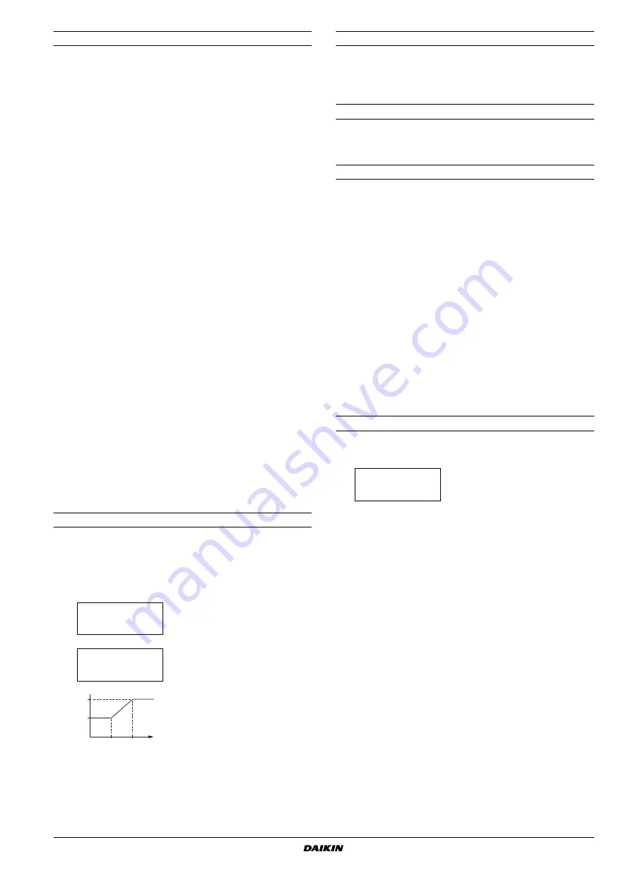
This allows the user to define a setpoint in function of an analog input
as mentioned above. Refer to
"Defining the setpoint signal setting" on
■
: to control the leaving water temperature of
a DICN system.
Defining the setpoint signal setting
The setpoint signal is used to change the setpoint by an external
analog input signal on a stand alone unit or on Slave 1 in a DICN
system.
Example
Setting of the probe offset
It is possible to enter a correction value for certain measured
temperatures (inlet water evaporator temperature and mixed outlet
water evaporator temperature). This in order to correct a possible
measurement fault. The default value of the probe offset, is equal to 0.
Steering the pump manually
There is the possibility to turn the pump on or off manually. This
means that when the unit is off the pump can also be turned on at
any time to check the pump.
Defining the BMS settings
The BMS parameters allowing communication between the unit and
the supervisory system can be modified with the
and
the
screen of the service menu. The BMS
parameters are:
screen:
■
: if set to
(yes), the unit can be
commanded and configured from a supervisory system. If set to
(no), the supervisory system can only read out values but
cannot modify them.
■
: used to address the PCB.
■
: indicates the communication protocol. If the optional
gateway is used to connect the units to a supervisory system,
the protocol is
.
screen:
■
: indicates the type of serial connection. The default
is set to
"#
.
■
: indicates the speed of communication. The default
setting of
$ %&'
must be used when the optional gateway
is connected.
Defining the thermostat settings
Defining the thermostat settings for inlet and outlet water temperature
of a, b and c can only be set in the service menu.
H
OW
TO
CONTINUE
After installation and connection of the packaged water-cooled water
chiller, the complete system should be checked and tested as
described in "Checks before initial start-up" in the operation manual
supplied with the unit.
Fill out the brief operation instructions form and fix it visibly near the
operating site of the refrigeration system.
in setpoints menu
➞
in service menu
➞
➞
Remark:
(
is only
available when input
(
,
,
!
or
!
) is selected.
Result
Display in readout menu
A
at 0 V
➝
12.0°C
) *
B
at 1 V
➝
12.0°C + 5.0°C = 17.0°C
) +*
, ) *
) *
) +*
) +*
-.
))
( ) #*
B
1 V
A
0 V
To define the thermostat settings of the
inlet and outlet water temperature.
-.
)" )# )*
)#*


