background image

D

–EIMHP01201-18_04EN - 7/24 

30.  the machinery must be installed in structures protected against atmospheric discharge according to the applicable 

laws and technical standards 

31.  do not bend or hit pipes containing pressurised fluids 
32.  it is not permitted to walk or rest other objects on the machines 
33.  the user is responsible for overall evaluation of the risk of fire in the place of installation (for example, calculation 

of the fire load) 

34.  during transport, always secure the unit to the bed of the vehicle to prevent it from moving about and overturning 
35.  the machine must be transported according to the regulations in force taking into account the characteristics of 

the fluids in the machine and the description of these on the safety data sheet 

36.  inappropriate transport can cause damage to the machine and even leaking of the refrigerant fluid. Before start-

up, the machine must be checked for leaks and repaired accordingly. 

37.  the  accidental  discharge  of  refrigerant  in  a  closed  area can  cause a  lack  of  oxygen  and, therefore,  the  risk  of 

asphyxiation:  install  the  machinery  in  a  well  ventilated  environment  according  to  EN  378-3  and  the  local 
regulations in force. 

38.  the installation must comply with the requirements of EN 378-3 and the local regulations in force; in the case of 

installations  indoors,  good  ventilation  must  be  guaranteed  and  refrigerant  detectors  must  be  fitted  when 
necessary. 


1.2 

General Description 

The unit you bought is a

n “air to water multipurpose”, a machine aimed to provide cooled and heated water on two separate 

loops  independently  during  all  year.  The  unit  is  aimed  to  operate  within  the  limits  described  in  the  following.  The  unit 
operation is based on vapour compression, condensation and evaporation according to reverse Carnot cycle. The main 
components are: 

Inverter driven Screw compressor to rise the refrigerant vapour pressure from evaporation pressure to condensation 
pressure 

Evaporator, where the low pressure liquid refrigerant evaporates to cool the water 

Condenser, where the high pressure vapour refrigerant condensates to heat the water 

Air heat exchanger, where the exceeding heating or cooling energy is  exchanged in the atmosphere thanks to the 
fans. 

Expansion  valves  allowing  to  reduce  the  pressure  of  condensed  liquid  from  condensation  pressure  to  evaporation 
pressure. 


1.3 

Receiving The Unit 

The unit must be inspected for any possible damage immediately upon reaching final place of installation. All components 
described in the delivery note must be inspected and checked.  
Should the unit be damaged, do not remove the damaged material and immediately report the damage to the transportation 
company and request  they inspect the unit..  
Immediately  report  the  damage  to  the  manufacturer  representative,  a  set  of  photographs  are  helpful  in  recognizing 
responsibility 
Damage must not be repaired before the inspection of the transportation company representative. 
Before  installing  the  unit,  check  that  the  model  and  power  supply  voltage  shown  on  the  nameplate  are  correct. 
Responsibility for any damage after acceptance of the unit cannot be attributed to the manufacturer. 
 

OPERATING LIMITS 

2.1 

Storing Storage 

Environmental conditions must be within the following limits: 
Minimum ambient temperature 

-20°C 

Maximum ambient temperature 

57°C 

Maximum R.H. 

95% not condensing 

Storing  below  the  minimum  temperature may  cause  damage  to components.  Storing above  the  maximum  temperature 
causes opening of safety valves. Storing in condensing atmosphere may damage electronic components.


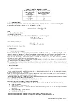
As a general rule, the unit should be operated with an evaporator water flow rate between 50% and 120% of nominal flow 
rate (at standard operating conditions), however check with the unit selection software the correct minimum and maximum 
allowed values for the specific model. 


STORAGE AND OPERATION OUT OF THE LIMITS BELOW MAY DAMAGE THE UNIT. 
In case of doubts contact manufacturer representative 


Summary of Contents for EWYD-4Z B

Page 1: ...ns REV 04 Date December 2019 Supersedes D EIMHP01201 18_03EN Multipurpose unit with Inverter Driven Single Screw Compressor EWYD 4ZB Refrigerant R 134a Installation Operation and Maintenance Manual D...

Page 2: ...connections 18 3 10 1 Cable requirements 18 3 10 2 Interconnection cables 18 3 10 3 Phase unbalance 19 4 OPERATION 19 Operator s responsibilities 19 5 MAINTENANCE 19 5 1 Routine maintenance 19 5 2 Uni...

Page 3: ...D EIMHP01201 18_04EN 3 24 Fig 1 Typical refrigerant circuit Water inlet and outlet are indicative Please refer to the machine dimensional diagrams for exact water connections...

Page 4: ...HEAT EXCHANGER COLD WATER 9 SHELL TUBE HEAT EXCHANGER HOT WATER 10 PRESSURE RELIEF VALVE Psat 24 5 bar CHANGEOVER DEVICE OPTIONAL 11 PRESSURE RELIEF VALVE Psat 15 5 bar CHANGEOVER DEVICE OPTIONAL 12...

Page 5: ...e electrical panel Single circuit unit Double circuits unit Label Identification 1 Manufacturer s logo 5 Cable tightening warning 2 Gas type 6 Non flammable gas symbol 3 Hazardous Voltage warning 7 Un...

Page 6: ...cuits close the section of the piping concerned and drain the fluid gradually to stabilise the pressure at the atmospheric level 12 do not use your hands to check possible refrigerant leaks 13 disable...

Page 7: ...our pressure from evaporation pressure to condensation pressure Evaporator where the low pressure liquid refrigerant evaporates to cool the water Condenser where the high pressure vapour refrigerant c...

Page 8: ...ntact factory for further details For operation with temperature at the outlet of the cold heat exchanger below 4 C the unit must operate with glycol mixture ethylene or propylene glycol The glycol pe...

Page 9: ...be able to operate outside the above envelope with compressors unloading Please contact factory for further details For operation with temperature at the outlet of the cold heat exchanger below 4 C th...

Page 10: ...ts around the unit 1 1 Noise The unit is a source of noise mainly due to rotation of compressors and fans The noise level for each model size is listed in sales documentation If the unit is correctly...

Page 11: ...ith 4 lifting points The drawing shows only the 6 fans version For the 4 fans version the lifting mode is the same Unit with 6 lifting points The drawing shows only the 12 fans version The lifting mod...

Page 12: ...D EIMHP01201 18_04EN 12 24 Unit with 8 lifting points...

Page 13: ...he condenser Limited installation space could reduce the normal air flow thus significantly reducing the machine s performance and considerably increasing consumption of electrical energy When decidin...

Page 14: ...mmended For further solutions please consult Daikin technicians The minimum distances reported above ensure functionality of the unit in most applications However there are specific situations which i...

Page 15: ...is working quite normally Fig 6 Multiple Chiller Installation In order to avoid the hot air recirculation due to dominant winds the installation where all units are aligned to the dominant wind is pre...

Page 16: ...as possible to the unit as in Fig 7 If the water filter is installed in another part of the water system the Installer has to guarantee the cleaning of the water pipes between the water filter and th...

Page 17: ...when the evaporator and or condenser water flow is lower than 50 of nominal flow rate For a proper unit operation the water flow rate of both heat exchangers evaporator and condenser must always recir...

Page 18: ...er harmonics such as an inverter or phase cut ground losses can increase to much higher values about 2 A The protections for the power supply system must be designed according to the values mentioned...

Page 19: ...g data for every installed unit Another record should also be kept of all the periodical maintenance and servicing activities If the operator notes abnormal or unusual operating conditions he is advis...

Page 20: ...nt leakage X Verify refrigerant flow using the liquid sight glass Sight glass full X Verify filter dryer pressure drop X Verify oil filter pressure drop Note 5 X Analyse compressor vibrations X Analys...

Page 21: ...it is necessary to wash periodically the frame surfaces with water and suitable detergents In case of part of unit frame paint came off it is important to stop its progressive deterioration by repain...

Page 22: ...nd its operating limits or not performing proper maintenance according to this manual can void the warranty Observe the following points in particular in order to conform to warranty limits 1 The unit...

Page 23: ...label supplied with the product as following instructions Any refrigerant charge for each circuit 1 2 3 added during commissioning the total refrigerant charge 1 2 3 calculate the greenhouse gas emis...

Page 24: ...nt and the products and services presented therein Specification are subject to change without prior notice Refer to the data communicated at the time of the order Daikin Applied Europe S p A explicit...

Reviews: