background image


D

–EIMHP01201-18_06EN - 26/27 


10  IMPORTANT INFORMATION REGARDING THE REFRIGERANT USED  

This product contains fluorinated greenhouse gases. Do not vent gases into the atmosphere. 
Refrigerant type:   

R134a 

GWP(1) value: 


1430 

(1)GWP = 


global warming potential 


10.1 

Factory And Field Charged Units Instructions  

 
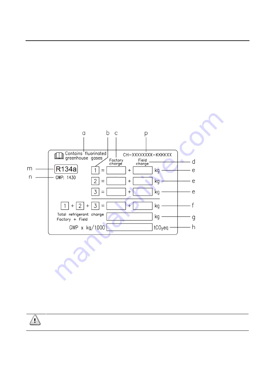
The refrigerant system will be charged with fluorinated greenhouse gases, and the factory charge(s) are recordered on the 
label, shown below, which is adhered inside the electrical panel. Periodic inspections for refrigerant leaks may be required 
depending on European or local legislation. Please contact your local dealer for more information. 
Do not vent gases into the atmosphere. 
 

1

 Fill in with indelible ink the refrigerant charge label supplied with the product as following instructions: 

Any refrigerant charge for each circuit (1; 2; 3) added during commissioning 

the total refrigerant charge (1 + 2 + 3)  

calculate the greenhouse gas emission with the following formula: 
GWP value of the refrigerant x Total refrigerant charge (in kg) / 1000 


a   Contains fluorinated greenhouse gases 
b   Circuit number 
c   Factory charge 
d   Field charge 
e   Refrigerant charge for each circuit (according to the number of circuits) 
f   Total refrigerant charge 
g  Total refrigerant charge (F Field) 
h   

Greenhouse gas emission 

of the total refrigerant charge expressed 

     as tonnes of CO2 equivalent 
m  Refrigerant type 
n   GWP = Global Warming Potential 
p   Unit serial number 


In Europe, the emission of greenhouse gases of the total refrigerant charge in the system (expressed 
in tonnes of equivalent CO

2

 ) is used to determine the frequency of maintenance interventions. Follow 

the applicable legislation. 


Summary of Contents for EWYD-4ZB

Page 1: ...al instructions REV 06 Date 11 2021 Supersedes D EIMHP01201 18_05EN Multipurpose unit with Inverter Driven Single Screw Compressor EWYD 4ZB Installation Operation and Maintenance Manual D EIMHP01201 1...

Page 2: ...r Cold and Hot side 18 3 11 Electric connections 19 3 11 1 Cable requirements 19 3 11 2 Phase unbalance 20 4 OPERATION 21 4 1 Operator s responsibilities 21 5 MAINTENANCE 21 5 1 Routine maintenance 21...

Page 3: ...D EIMHP01201 18_06EN 3 27 Fig 1 Typical refrigerant circuit Water inlet and outlet are indicative Please refer to the machine dimensional diagrams for exact water connections...

Page 4: ...HEAT EXCHANGER COLD WATER 9 SHELL TUBE HEAT EXCHANGER HOT WATER 10 PRESSURE RELIEF VALVE Psat 24 5 bar CHANGEOVER DEVICE OPTIONAL 11 PRESSURE RELIEF VALVE Psat 15 5 bar CHANGEOVER DEVICE OPTIONAL 12...

Page 5: ...e electrical panel Single circuit unit Double circuits unit Label Identification 1 Manufacturer s logo 5 Cable tightening warning 2 Gas type 6 Non flammable gas symbol 3 Hazardous Voltage warning 7 Un...

Page 6: ...um pressure limit PS of the water circuit of the unit 11 before removing parts on the pressurised water circuits close the section of the piping concerned and drain the fluid gradually to stabilise th...

Page 7: ...refrigerant detectors must be fitted when necessary 1 2 General Description The unit you bought is an air to water multipurpose a machine aimed to provide cooled and heated water on two separate loop...

Page 8: ...an evaporator water flow rate between 50 and 120 of nominal flow rate at standard operating conditions however check with the unit selection software the correct minimum and maximum allowed values fo...

Page 9: ...h size Opt 142 provides EC motors fans The performances will differ from the standards 2 3 Operating limits Water to Water operation Recovery Mode The following options must be included according to t...

Page 10: ...arapets or railings or areas not complying with the clearance requirements around the unit 3 2 Noise and sound protection The unit is a source of noise mainly due to rotation of compressors and fans T...

Page 11: ...il The unit must be installed on a robust and perfectly level foundation should the unit be installed on balconies or roofs it might be necessary to use weight distribution beams Fig 3 Lifting Unit wi...

Page 12: ...D EIMHP01201 18_06EN 12 27 Unit with 8 lifting points...

Page 13: ...VM Installation such as in the figure above must always be avoided In case the AVM s are not adjustable the flatness of the unit frame must be guaranteed by using metal plate spacers Before unit commi...

Page 14: ...their air cooled condensers the units are less affected by poor air circulation conditions Also the software has particularly the ability to compute the machine s operating conditions to optimise the...

Page 15: ...1 is performing normally without any ambient over temperature Unit N 2 is working in a warmed ambient The first circuit from the left is working with air recirculating from Unit 1 and the second circ...

Page 16: ...n order to reduce transmission of vibrations to the structures 2 Isolating valves to isolate the unit from the water system during maintenance 3 Flow switch in order to protect the unit must be protec...

Page 17: ...ss can be used during maintenance to isolate the heat exchanger without disrupting flow to other units Any damage due to the presence of foreign bodies or debris in the shell tube heat exchangers will...

Page 18: ...ich must be electrically connected to terminals shown in the wiring diagram Flow switch has to be tune to intervene when the evaporator and or condenser water flow is lower than 50 of nominal flow rat...

Page 19: ...neral switch The electrical connection of the panel must be carried out maintaining the correct sequence of the phases Refer to the specific wiring diagram for the unit you have bought Should the wiri...

Page 20: ...11 2 Phase unbalance In a three phase system the excessive imbalance between the phases is the cause of the engine overheating The maximum permitted voltage unbalance is 3 calculated as follows 100 wh...

Page 21: ...on the system the personnel shall assure that all security precautions have been taken Neglecting unit maintenance in these environments could degrade all parts of the units coils compressors frames p...

Page 22: ...ivities Weekly Monthly Note 1 Yearly Seas Onal Note 2 Refrigeration circuit Check for any refrigerant leakage X Verify refrigerant flow using the liquid sight glass Sight glass full X Verify filter dr...

Page 23: ...akage X Verify refrigerant flow using the liquid sight glass Sight glass full X Verify filter dryer pressure drop X Verify oil filter pressure drop Note 5 X Analyse compressor vibrations X Analyse com...

Page 24: ...tors is recommended This operation must be done only by qualified technicians Replacement must be carried out through the following procedure Power off the unit Wait for 5 minutes before opening the i...

Page 25: ...hanical electrical or electronic must be disabled or overridden 5 The water used for filling the water circuit must be clean and suitably treated A mechanical filter must be installed at the point clo...

Page 26: ...label supplied with the product as following instructions Any refrigerant charge for each circuit 1 2 3 added during commissioning the total refrigerant charge 1 2 3 calculate the greenhouse gas emis...

Page 27: ...e of its content and the products and services presented therein Specification are subject to change without prior notice Refer to the data communicated at the time of the order Daikin Applied Europe...

Reviews: