Operating Manual
D-EOMCP00104-14_01EN
EWYD_BZ
23/35
•
Absorbed inverter current
The compressor load is inhibited if, the absorbed inverter current is above an adjustable threshold .
The compressor is unloaded if the absorbed inverter current is above the inhibit threshold of an adjustable
percentage.
5.21
Unit limiting
Unit load may be limited by the following inputs:
•
Unit current
The unit load is inhibited if the absorbed current is near to a maximum current setpoint (within -5% from
setpoint)
The unit is unloaded if the absorbed current is higher than a maximum current setpoint
•
Demand limit
The unit load is inhibited if the unit load (measured by slide valve sensors or calculated as described) is near
to a maximum load setpoint (within -5% from setpoint)
The unit is unloaded if the unit load is higher than the maximum load setpoint.
The maximum load setpoint may be derived by a 4-20 mA input (4mA
→
limit=100%; 20 mA
→
limit=0%); or
from a numeric input coming from monitoring system (network demand limit).
•
SoftLoad
At unit startup (when the first compressor stats) a temporary demand limit may be set up to a time expired.
5.22
Evaporator pumps
An evaporator pump is foreseen in the base configuration while a second pump is an optional. When the two pumps are
selected, the system will automatically start the pump with lower operating hours each time a pum p has to be started. A
fixed starting sequence may be set. A pump is started when the unit is switched on; within 30 sec an evaporator flow switch
must close otherwise and “Evaporator Flow Alarm” will rise. The alarm is automatically reset for three times if the evaporator
flow switch closes for more than 30 seconds. Starting from the fourth alarm it has to be reset manually.
5.23
Fans control
Fans control is used to manage condensation pressure in cooling, cooling glycol or ice mode and evaporating pressu re in
heating mode. In both cases the fans may be managed to control:
•
Condensation or evaporation pressure,
•
Pressure ratio,
•
Pressure difference between condensation and evaporation.
Four control methods are available:
•
Fantroll,
•
Variable speed driver,
•
Speedtroll.
5.23.1
Fantroll
A step control is used; fan steps are activated or deactivated to keep compressor operating conditions within the allowed
envelope. Fan steps are activated or deactivated keeping condensing (or evaporating pressure) change to a minimum; to
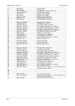
do this one next fan is started or stopped at time. Fans are connected to steps (digital outputs) according to the scheme in
table below
Fans connection to steps
N° of fans per circuit
2
3
4
5
6
7
8
9
Step
Fans on the step
1
1
1
1
1
1
1
1
1
2
2
2
2
2
2
2
2
2
3
3
3,4
3,4
3,4
3,4
3,4
3,4
4
5
5,6
5,6
5,6
5,6
5
7
7,8
7,8,9


