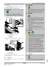
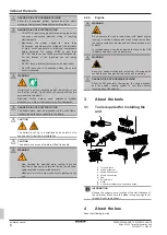
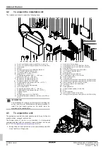
background image

7 Installation

Installation manual

18

EZESHP20 EZLSHP20AUAW1B

Exigo E1500 Trailer Refrigeration Unit

4P726857-1 – 2023.03

f

Hand pump

7.6.3

To install the fuel pump

Installing the fuel pump is left to the expertise of the bodybuilder.

INFORMATION

Check  the  instruction  on  the  pump  body  (oulet/inlet,  wire
colours)  to  assure  correct  connection  of  wirings  and  fuel
line.

A typical installation, using a mounting bracket is shown below.

c

d

c

b

d c

a

c

b

e

a

Fuel pump

b

Bolt

c

Flat washer

d

Lock nut

e

Bracket

7.6.4

To install the fuel lines

Installing the fuel lines is left to the expertise of the bodybuilder.

An  installation  kit  is  supplied  with  the  unit,  see 

"4.2  To  unpack  the

installation kit"

 [

4

 8].

The  installation  kit  contains  fuel  lines  and  connectors.  Any  required
fixing materials and (if necessary) extra protection of the lines must
be provided by the bodybuilder.

INFORMATION

ALWAYS  use  hydraulic  thread  sealant  as  delivered  with
the installation kit to seal the fuel connections.

a

c

b

a

Fuel tank suction and return pipe (L=720 mm)

b

Straight female adapter (NPS ¼" → Ø10 mm)

c

Fuel supply line (flexible tubing - outside Ø10 mm, black
color)

1

Connect  the  adapter  (b)  to  the  suction  pipe  of  the  fuel  tank
suction and return pipe (a).

2

Connect the fuel supply line (c) to the adapter (b).

3

Guide the fuel supply line (c) towards the diesel pre-filter (d).

c

d

e

f

g

h

i

j

d

Diesel pre-filter with water separator

e

Nipple (NPS ¼" → M16)

f

Straight parallel male adapter (Ø10 mm → NPT ¼")

g

Nipple (NPS ¼" → M16)

h

Straight parallel male adapter (Ø10 mm → NPT ¼")

i

Fuel supply line (flexible tubing - outside Ø10 mm, black
color)

j

Diesel pump

4

Screw  the  nipple  (e)  into  the  diesel  pre-filter  (d)  on  the  inlet
side.

5

Screw the adapter (f) into the nipple (e).

6

Cut the fuel supply line (c) to length.

7

Connect the fuel supply line (c) coming from the fuel tank to the
adapter (f).

8

Screw  the  nipple  (g)  into  the  diesel  pre-filter  (d)  on  the  outlet
side.

9

Screw the adapter (h) into the nipple (g).

Summary of Contents for Exigo E1500

Page 1: ...Installation manual Exigo E1500 Trailer Refrigeration Unit English Installation manual Exigo E1500 Trailer Refrigeration Unit EZESHP20AUAW1B EZLSHP20AUAW1B ...

Page 2: ...t the user has the printed documentation and ask him her to keep it for future reference Target audience Authorised installers Documentation set This document is part of a documentation set The complete set consists of Installation manual Installation instructions Format Paper in the box of the unit Operation manual Quick guide for basic usage Format Paper in the box of the unit Latest revisions o...

Page 3: ... the engine cooling system the evaporator defrost heaters and the water discharge heater to cool down before touching any of these parts DANGER RISK OF BURNING SCALDING Allow the engine the engine exhaust and the engine cooling system to cool down before performing any fluid change WARNING Improper installation or attachment of equipment or accessories could result in electrical shock short circui...

Page 4: ... to eyes respiratory system and skin and can ignite if an open flame is in the area CAUTION Diesel is a polluting substance Any diesel leaking from the fuel system may not be released in the environment WARNING When the unit is operating a magnetic field is generated This can disturb the functioning of cardiac devices like pacemakers and defibrillators People who have such devices implanted must s...

Page 5: ...erant is required WARNING Refrigerant under pressure can escape due to breaks in the cooling system or during work on the cooling system WARNING Take sufficient precautions in case of refrigerant leakage If refrigerant gas leaks ventilate the area immediately Possible risks Excessive refrigerant concentrations in a closed room can lead to oxygen deficiency Toxic gas might be produced if refrigeran...

Page 6: ...to the frame CAUTION The battery is set up in a small space be careful not to cause a short circuit during installation CAUTION The battery is heavy and therefore difficult to handle WARNING After finishing the electrical work confirm that each electrical component and terminal inside the electrical components box is connected securely Make sure all covers are closed before starting up the unit 2 ...

Page 7: ...ed immediately to the claims agent of the carrier At delivery the installation kit MUST be checked for damage and completeness Any damage or missing part MUST be reported immediately to the claims agent of the carrier Bring the packed unit as close as possible to its final installation position to prevent damage during transport When handling the unit take into account the following Fragile handle...

Page 8: ...ad screw M6 20 UNI 7380 INOX m Flat washer Ø8 24 UNI 6593 INOX aj Hexagon socket pan head screw M5 20 UNI 7380 INOX n Straight parallel male adapter Ø10 mm NPT ak Grower washer Ø5 UNI 1751 A2 70 INOX o Nipple NPS M16 al Flat washer Ø5 10 UNI 6592 INOX p Diesel pre filter with water separator am IoT module q Lock nut M8 INOX an Cable gland 80722 r Straight female adapter NPS Ø8 mm ao Hydraulic thre...

Page 9: ...ice and lifting slings 2 Standing on a ladder or work stand hook the slings b onto the fixing points c b c b c b Sling c Fixing points A1 3 Lift the unit with a lifting device e g overhead crane 4 Remove the plastic film from around the unit WARNING Tear apart and throw away plastic packaging bags so that nobody especially NOT children can play with them Possible consequence suffocation 5 About th...

Page 10: ...e bodybuilder may opt for a different fixing system but it must be at least as safe or safer INFORMATION This manual only describes installation instructions specific to this unit For carrying out mechanical work on the cold room and trailer the instructions of the cold room trailer manufacturer must always be followed INFORMATION Double loading doors are recommended for a cold room trailer These ...

Page 11: ...rtise of the bodybuilder self tapping screws d or a large head rivets c are both possibilities included in the installation kit that is supplied with the unit see 4 2 To unpack the installation kit 48 The size of the holes must fit the chosen option A typical installation is shown below 5 Install the heat shield b on the cold room using the self tapping screws d or using large head rivets c c b a ...

Page 12: ...ng the door micro switch and cold room light 3 Installing the eventual option s 4 Installing the fuel pump 5 Connecting the fuel lines INFORMATION This manual only describes installation instructions specific to this unit For carrying out mechanical work on the cold room and trailer the instructions of the cold room trailer manufacturer must always be followed INFORMATION In some cases the install...

Page 13: ...e freedom of movement the unit must remain suspended The lifting slings should not be removed until the installation of the 8 bolts washers and nuts is completed and the unit is in its correct and final position 3 Place a washer e and lock nut f on each of the 8 bolts c and hand tighten the lock nuts f e c f c Exigo frame bolt e Flat washer Ø13 35 5 DIN 6340 INOX f Lock nut M12 DIN 982 ZINC See be...

Page 14: ...e rotated to give access to the bolt location in the bottom right hand corner inside the unit NOTICE The wiring of the controller is connected to the unit Be careful not to break the wiring while rotating or removing the controller 9 Open unit s service doors 10 Loosen the lock nuts k The screws l and nuts k do not have to be removed j n k l m k l m m k l m k l j Controller k Lock nut l Screw m Wa...

Page 15: ...1 Standing on an industrial ladder or other safe platform position the grids c and d on the top panel e 2 Install the screws a and washers b and tighten them b 8 c 8 a f e b 8 c 8 d 8 d 8 a Hexagon socket pan head screw M6 20 UNI 7380 INOX b Contact washer Ø6 1 18 1 4 INOX c Upper right grid d Upper left grid e Top panel 7 3 To install the bottom plate The Bottom plate of the unit is not installed...

Page 16: ... required NOTICE Incorrect connection of the drain hose might cause leaks and damage the installation space and surroundings a a a Drain hose 7 5 Battery 1 Remove the nuts c and washers d from the threaded rods e 2 Remove the brackets a together with the relay box b b b e d c a a 1 2 a Bracket b Relay box c Nut d Washer e Threaded rod CAUTION The battery is set up in a small space be careful not t...

Page 17: ...as indicated in the manual can be used Do not use fittings from other suppliers WARNING If diesel leaks from the fuel system it evaporates These vapors are irritating to eyes respiratory system and skin and can ignite if an open flame is in the area CAUTION Diesel is a polluting substance Any diesel leaking from the fuel system may not be released in the environment 7 6 1 To install the fuel tank ...

Page 18: ...uilder INFORMATION ALWAYS use hydraulic thread sealant as delivered with the installation kit to seal the fuel connections a c b a Fuel tank suction and return pipe L 720 mm b Straight female adapter NPS Ø10 mm c Fuel supply line flexible tubing outside Ø10 mm black color 1 Connect the adapter b to the suction pipe of the fuel tank suction and return pipe a 2 Connect the fuel supply line c to the ...

Page 19: ...e undercarriage of the trailer 21 Using the Cutter for multilayer and pneumatic hoses cut the fuel supply line o coming from the diesel pump to length 22 Connect the fuel supply line to the equal straight connector p coming out of the unit by pushing it firmly in the connector Check the correct connection by pulling the line 23 Connect the adapter q to the return pipe of the fuel tank suction and ...

Page 20: ...cket of the unit cable The fuel pump cable coming out of the unit is labelled Fuel pump The fuel pump is connected to the X50Y connector FUEL PUMP 0BAT 76 1 2 X50Y BN 2x1 5 W25 BU BN 2x1 5 W25 7 7 To install the Iot module a a IoT module 1 Install the Iot module a 2 Plug the 2 pin connector of the connection cable in the socket of the unit cable The Iot module is connected to the X7Y connector 7 8...

Page 21: ...in data logger 1 Install the cold chain data logger a 2 Plug the 2 pin connector of the connection cable in the socket of the unit cable The cold chain data logger is connected to the X104Y connector INFORMATION Full installation instructions are delivered with the option kit 7 10 To install the fuel level probe a b a Connector b Fuel level probe 1 Install the fuel level probe b 2 Guide the electr...

Page 22: ...e sure they are not damaged during installation and that there are no visible leakages 2 Check that all auxiliary components are installed correctly and that there are no visible leakages Fuel tank Fuel pre filter Fuel pump Fuel lines and connections WARNING If diesel leaks from the fuel system it evaporates These vapors are irritating to eyes respiratory system and skin and can ignite if an open ...

Page 23: ...printed documentation and ask him her to keep it for future reference Inform the user that he can find the complete documentation at the URL mentioned earlier in this manual Explain the user how to properly operate the system and what to do in case of problems Show the user what to do for the maintenance of the unit 10 Disposal The metal pallet on which the unit is fixed at delivery may be returne...

Page 24: ...e used can bear the weight of the unit Weight of the Exigo 1500 unit 730 kg Weight of the Exigo 1500 unit with the special transport pallet 776 kg 12 Glossary Dealer Sales distributor for the product Authorised installer Technical skilled person who is qualified to install the product Bodybuilder Technical skilled person who is qualified to install the product on a cold room trailer User Person wh...

Page 25: ...25 EZESHP20AUAW1B EZLSHP20AUAW1B Exigo E1500 Trailer Refrigeration Unit 4P726857 1 2023 03 Field supply Equipment NOT made by Daikin that can be combined with the product according to the instructions in the accompanying documentation ...

Page 26: ......

Page 27: ......

Page 28: ...4P726857 1 2023 03 Copyright 2023 Daikin 4P726857 1 0000000X Verantwortung für Energie und Umwelt ...

Reviews: