SiUS071735EA
Field Settings
Trial Operation and Field Settings
122
4.3
MAIN/SUB and Address Setting for Wireless Remote
Controller
Outline
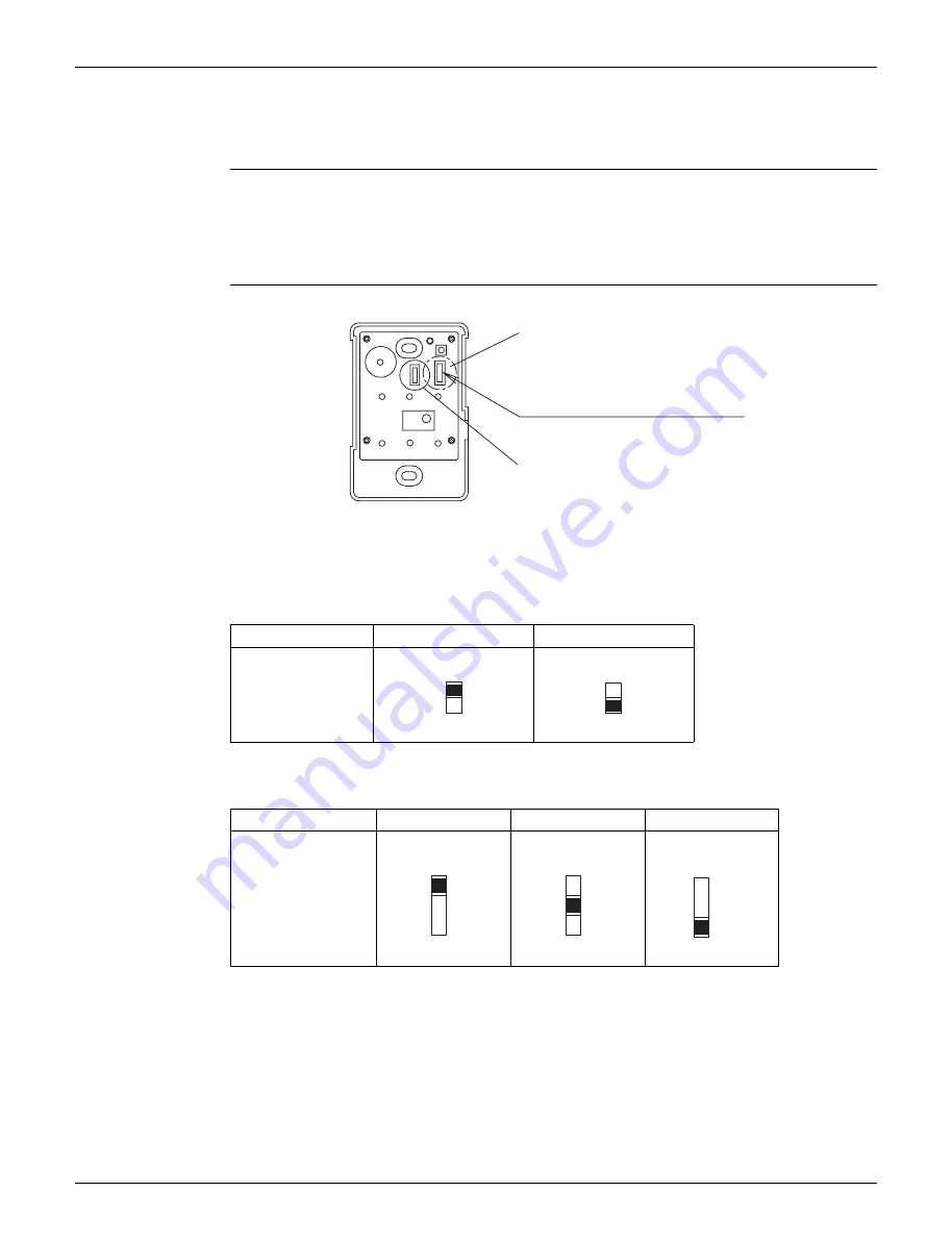
If setting multiple wireless remote controllers to operate in one room, perform address setting
for the receiver and the wireless remote controller.
If using both a wired remote controller and a wireless remote controller with 1 indoor unit,
change the MAIN/SUB switch of the signal receiver PCB.
Signal Receiver
PCB Setting
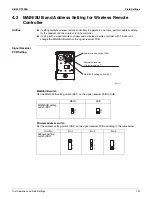
MAIN/SUB switch
Set the MAIN/SUB setting switch (SS1) on the signal receiver PCB to SUB.
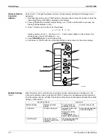
Wireless address switch
Set the address setting switch (SS2) on the signal receiver PCB according to the table below.
MAIN
SUB
MAIN/SUB setting
switch (SS1)
Unit No.
No.1
No.2
No.3
Address setting
switch (SS2)
Setting the receiver
(lt is factory set to “1”)
Address setting switch (SS2)
MAIN/SUB setting switch (SS1)
(R24951)
M
S
M
S
1
2
3
1
2
3
1
2
3
Summary of Contents for FDMQ-R Series
Page 12: ...SiUS071735EA 1 List of Functions Part 1 List of Functions 1 Functions 2...
Page 14: ...SiUS071735EA 3 Specifications Part 2 Specifications 1 Specifications 4...
Page 120: ...Check SiUS071735EA 109 Service Diagnosis 15 18 24 class R25105 1 2 3 4 Multimeter...
Page 122: ...Check SiUS071735EA 111 Service Diagnosis 15 18 24 class R20704 W V U DC_P1 DC_N1...
Page 140: ...Piping Diagrams SiUS071735EA 129 Appendix RX24RMVJU A 3D092249A...

