SiUS071735EA
Field Settings
Trial Operation and Field Settings
124
After Setting
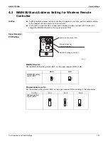
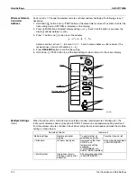
Stick the Unit No. label on the receiver and the back of the wireless remote controller.
Note:
Set the Unit No. of the receiver and the wireless remote controller to be the equal. If the settings
differ, the signal from the remote controller cannot be transmitted.
4.4
Facility Setting (cooling at low outdoor temperature)
Outline
This function is limited only for facilities (the target of air conditioning is equipment such as
computers). Never use it in a residence or office (the space where there is a human).
Details
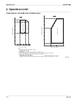
Cutting jumper 6 (J6) on the circuit board will extend the operation range to –10°C (14°F).
Installing an air direction adjustment grille (sold separately) will further extend the operation
range to –20°C (–4°F). In these cases, the unit will stop operating if the outdoor temperature
falls below –20°C (–4°F), restarting once the temperature rises above this level.
1. Remove the top plate of the outdoor unit. (09/12 class: 3 screws, 15/18/24 class: 6 screws)
2. Remove the front plate. (09/12 class: 4 screws, 15/18/24 class: 8 screws)
3. Cut the jumper (J6) of the PCB inside.
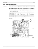
For the location of the jumper, refer to pages 13, 14.
Caution
Replace the PCB if you accidentally cut a wrong jumper.
Jumpers are necessary for electronic circuit. Improper operation may occur if you cut any of them.
Caution
If the outdoor unit is installed where the heat exchanger of the unit is exposed to direct wind,
provide a windbreak wall.
Intermittent noises may be produced by the indoor unit due to the outdoor fan turning on and off
when using facility settings.
Do not place humidifiers or other items which might raise the humidity in rooms where facility
settings are being used.
A humidifier might cause dew jumping from the indoor unit outlet vent.
Cutting jumper 6 (J6) sets the indoor fan tap to the highest position. Notify the user about this.
1
Unit No. label (5)
Wireless remote
controller (2)
(R25081)
Summary of Contents for FDMQ-R Series
Page 12: ...SiUS071735EA 1 List of Functions Part 1 List of Functions 1 Functions 2...
Page 14: ...SiUS071735EA 3 Specifications Part 2 Specifications 1 Specifications 4...
Page 120: ...Check SiUS071735EA 109 Service Diagnosis 15 18 24 class R25105 1 2 3 4 Multimeter...
Page 122: ...Check SiUS071735EA 111 Service Diagnosis 15 18 24 class R20704 W V U DC_P1 DC_N1...
Page 140: ...Piping Diagrams SiUS071735EA 129 Appendix RX24RMVJU A 3D092249A...

