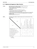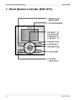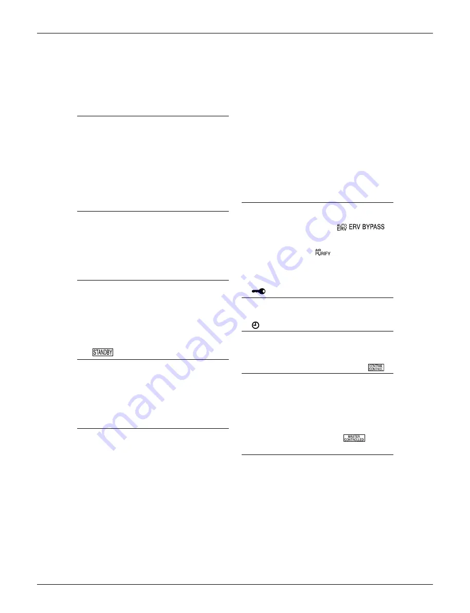
Wired Remote Controller (BRC1E73)
SiUS071735EA
49
Remote Controller
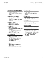
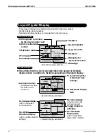
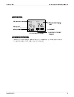
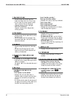
1. Operation mode
2. Fan Speed
3. Setpoint
If ventilation icon is displayed in this field:
5. Message
“Error: Push Menu button”
“Warning: Push Menu button”
“Time to clean filter”
“Time to clean element”
“Time to clean filter & element”
6. Ventilation
7. Key Lock
8. Scheduled
9. Under Centralized control “ ”
4. Stand by for Defrost/Hot start
“ ”
Used to display the current operation
mode: Cool, Heat, Vent, Fan, Dry or Auto.
In Auto mode, the actual operation mode
(Cool or Heat) will be also displayed.
Operation mode cannot be changed
when OFF is displayed.
Operation mode can be changed after
starting operation.
Displayed if an error or warning is detected.
Displayed as a reminder when it is time to
clean the filter and/or element.
Displayed when the key lock is set.
Displayed if the Schedule or Off timer is
enabled.
Displayed if the system is under the
management of a multi-zone controller
(Optional) and the operation of the system
through the remote controller is limited.
Displayed when another indoor unit on the
system has the authority to change the
operation mode between cool and heat.
Displayed when an energy recovery
ventilator is connected.
Ventilation Mode icon.“
”
These icons indicate the current ventilation
mode (ERV only) (AUTO, ERV, BYPASS).
Air Purify ICON “
”
This icon indicates that the air purifying unit
(Optional) is in operation.
Used to display the fan speed that is set for
the indoor unit.
The fan speed will not be displayed if the
connected model does not have fan speed
control functionality.
Used to display the setpoint for the indoor
unit.
Use the Celsius/Fahrenheit item in the
main menu to select the temperature unit
(Celsius or Fahrenheit).
Indicates that an energy recovery ventilator
(ERV) is connected.
For details, refer to the Operation Manual of
the ERV.
Displayed for a few seconds when an
Operation button is pressed and the indoor
unit does not provide the corresponding
function.
In a remote control group, the message will
not appear if at least one of the indoor units
provides the corresponding function.
•
•
•
•
•
•
•
•
•
•
•
•
•
•
•
•
•
•
•
The following messages may be
displayed.
“This function is not available”
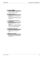
10. Changeover controlled by the
master indoor unit “ ”
(VRV only)
Summary of Contents for FDMQ-R Series
Page 12: ...SiUS071735EA 1 List of Functions Part 1 List of Functions 1 Functions 2...
Page 14: ...SiUS071735EA 3 Specifications Part 2 Specifications 1 Specifications 4...
Page 120: ...Check SiUS071735EA 109 Service Diagnosis 15 18 24 class R25105 1 2 3 4 Multimeter...
Page 122: ...Check SiUS071735EA 111 Service Diagnosis 15 18 24 class R20704 W V U DC_P1 DC_N1...
Page 140: ...Piping Diagrams SiUS071735EA 129 Appendix RX24RMVJU A 3D092249A...

