SiUS071735EA
Troubleshooting
Service Diagnosis
72
4.9
Signal Transmission Error (Between Indoor Unit and
Remote Controller)
Error Code
U5
Method of Error
Detection
In case of controlling 1 indoor unit with 2 remote controllers, check the system using microcomputer
if signal transmission between indoor unit and remote controller (main and sub) is normal.
Error Decision
Conditions
Normal transmission does not continue for specified period.
Supposed
Causes
Connection of 2 main remote controllers (when using 2 remote controllers)
Defective indoor unit PCB
Defective remote controller
Transmission error caused by noise
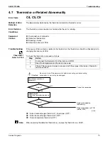
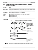
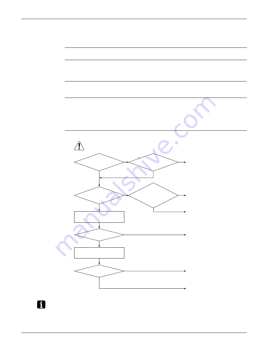
Troubleshooting
Note:
For the way to change MAIN/SUB setting of remote controllers, refer to pages 120 and 122.
Caution
Be sure to turn off the power switch before connecting or disconnecting
connectors, or parts may be damaged.
Are both
remote controllers set to
MAIN?
Do the
service monitors of all
the indoor units
blink?
Does
operation return
to normal when the
power is turned off
momentarily?
NO
NO
YES
YES
NO
Replace the indoor unit
PCB (control PCB).
Set 1 remote controller to
SUB; turn the power supply
off once and then back on.
When using both wired and
wireless remote controllers for
1 indoor unit, make sure to set
the wireless remote controller
to SUB.
There is possibility of
malfunction caused by noise.
Check the surrounding area
and turn on again.
There is possibility of
malfunction caused by noise.
Check the surrounding area
and turn on again.
Normal
Normal
NO
NO
Using
2 remote controllers
for 1 indoor unit?
YES
YES
YES
Replace the remote controller.
Return to normal?
Return to normal?
NO
Replace the indoor unit PCB.
YES
(R24057)
Summary of Contents for FDMQ-R Series
Page 12: ...SiUS071735EA 1 List of Functions Part 1 List of Functions 1 Functions 2...
Page 14: ...SiUS071735EA 3 Specifications Part 2 Specifications 1 Specifications 4...
Page 120: ...Check SiUS071735EA 109 Service Diagnosis 15 18 24 class R25105 1 2 3 4 Multimeter...
Page 122: ...Check SiUS071735EA 111 Service Diagnosis 15 18 24 class R20704 W V U DC_P1 DC_N1...
Page 140: ...Piping Diagrams SiUS071735EA 129 Appendix RX24RMVJU A 3D092249A...


