Service Diagnosis
SiUS071735EA
57
Service Diagnosis
3. Service Diagnosis
3.1
Wired Remote Controller (BRC1E73)
Relations
Between Modes
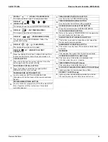
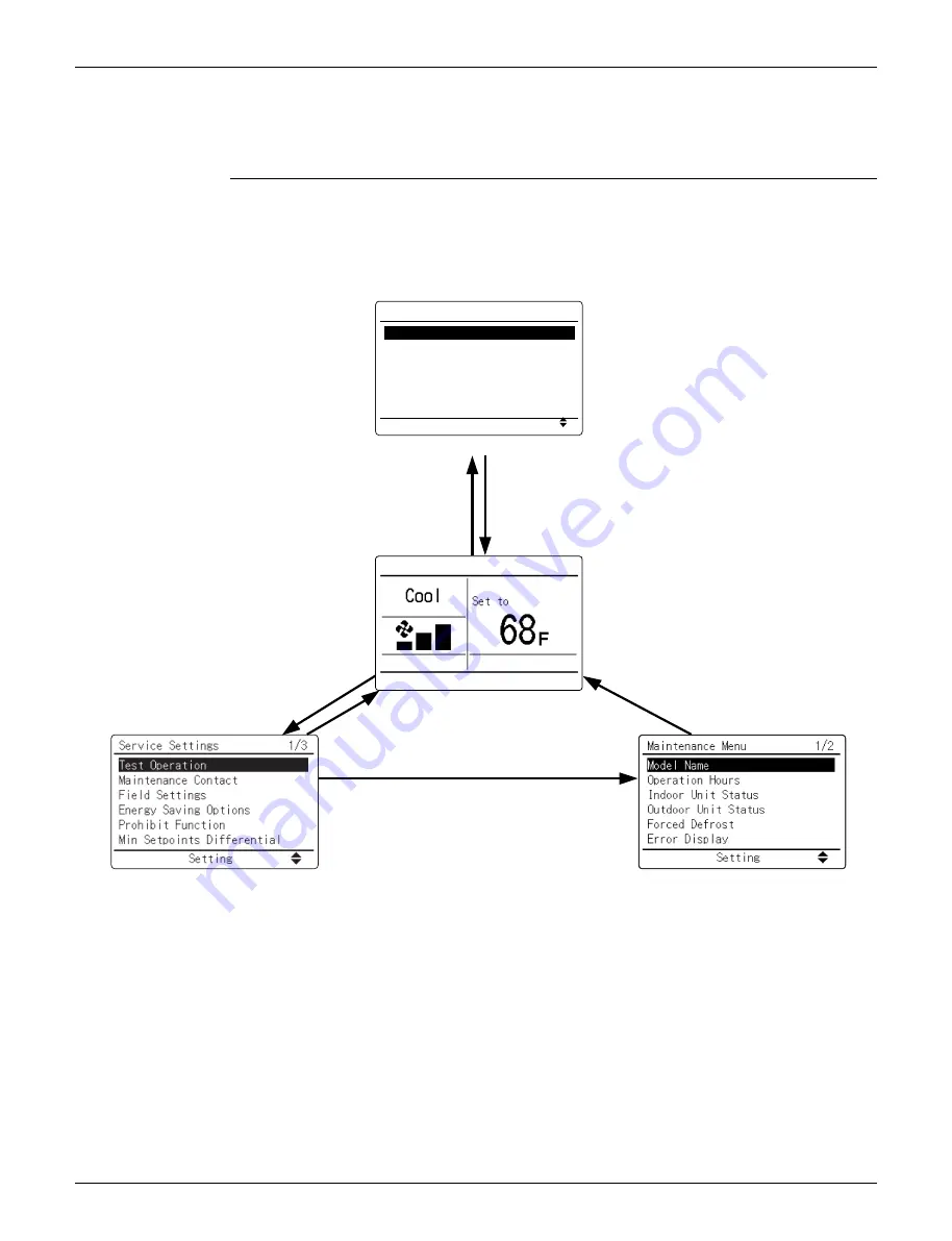
On power-up, the message “
Checking the connection. Please standby.
” will be displayed on the
remote controller screen temporarily and then the basic screen will be displayed. To access a mode
from the basic screen, refer to the figure below.
When any of the operation buttons is pressed, the backlight will come on and remain lit for about 30
seconds. Be sure to press a button while the backlight is on.
The items shown on the remote controller menu are different depending on the connected indoor
unit model.
Basic screen
Main Menu screen
Service Settings
screen
Maintenance Menu
screen
Setting
Main Menu
Airflow Direction
Individual Airflow Direction
Ventilation
Schedule
Off Timer
Celsius / Fahrenheit
1/3
Main Menu
• Airflow Direction
• Individual Airflow Direction
• Ventilation
• Schedule
• Off Timer
• Celsius / Fahrenheit
• Filter Auto Clean
• Maintenance Information
• Configuration
• Current Settings
• Clock & Calendar
• Daylight Saving Time
• Language
Press
Cancel
button once.
Press
Menu/OK
button once.
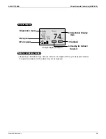
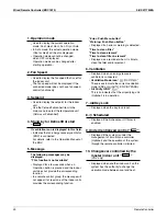
Basic Screen
• Operation mode changeover
• Fan speed control
• Menu display
• Confirmation of each setting
• On
• Off
• Cancel
• Operation lamp
Press
Cancel
button
for 4 seconds or more.
Press
Cancel
button once.
Press
Cancel
button
for 4 seconds or more.
Press
Cancel
button once.
Maintenance Menu
• Model Name
• Operation Hours
• Indoor Unit Status
• Outdoor Unit Status
• Forced Defrost
• Error Display
• Swap Unit No.
• Addressed Sensor Value
Service Settings
• Test Operation
• Maintenance Contact
• Field Settings
• Energy Saving Options
• Prohibit Function
• Min Setpoints Differential
• Outdoor unit AirNet Address
• Error History
• Indoor Unit Status
• Outdoor Unit Status
• Forced Fan ON
• Switch Main Sub Controller
• Filter Indicator
• Brush / Filter Ind.
• Disable Filter Auto Clean
(R23948)
Summary of Contents for FDMQ-R Series
Page 12: ...SiUS071735EA 1 List of Functions Part 1 List of Functions 1 Functions 2...
Page 14: ...SiUS071735EA 3 Specifications Part 2 Specifications 1 Specifications 4...
Page 120: ...Check SiUS071735EA 109 Service Diagnosis 15 18 24 class R25105 1 2 3 4 Multimeter...
Page 122: ...Check SiUS071735EA 111 Service Diagnosis 15 18 24 class R20704 W V U DC_P1 DC_N1...
Page 140: ...Piping Diagrams SiUS071735EA 129 Appendix RX24RMVJU A 3D092249A...

