• Indoor Units • R410A • FLXS-BAVMB
2
• Split Sky Air • Indoor Units
4
2
Specifications
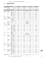
Piping
connections
Liquid (OD)
Diameter
(OD)
mm
6.4
6.4
6.35
6.35
Gas
Diameter
(OD)
mm
9.5
9.5
12.7
12.7
Drain
Diameter
(OD)
mm
18
18
18
18
Heat Insulation
Both liquid and gas pipes
Air Filter
Removable/washable/Mildew proof
Air direction control
Left, right, up and downwards
Temperature control
Microcomputer control
Standard
Accessories
Item
Installation and operation manual
Quantity
1
1
1
1
Item
Infrared remote control
Quantity
1
1
1
1
Item
Batteries
Quantity
2
2
2
2
Item
Remote control holder
Quantity
1
1
1
1
Item
Air purification filter
Quantity
1
1
1
1
Item
Heat insulation tube
(refrigerant pipe)
Heat insulation tube
(refrigerant pipe)
Heat insulation tube
(refrigerant pipe)
Heat insulation tube
(refrigerant pipe)
Quantity
1
1
2
2
Item
Mounting plate
Quantity
1
1
1
1
Item
Side cover
Quantity
2
2
2
2
Item
Binding band
Quantity
4
4
4
4
Item
Photocatalytic deodorizing filter
Quantity
1
1
1
1
Item
Extension auxiliary pipe
Extension auxiliary pipe
Quantity
2
2
Notes
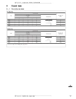
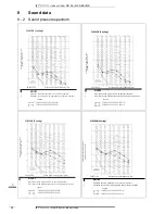
Sound values are measured in an anechoic room.
Sound pressure level is a relative value, depending on the distance and acoustic environment. For more details,
please refer to sound level drawings of this chapter.
The sound power level is an absolute value indicating the power which a sound source generates.
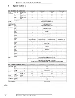
2-3 ELECTRICAL SPECIFICATIONS
FLXS25BAVMB
FLXS35BAVMB
FLXS50BAVMB
FLXS60BAVMB
Power Supply
Name
VM
Phase
1
1
1
1
Frequency
Hz
50/60
Voltage
V
220-240/220-230
Current
Nominal
running current
(RLA)
Cooling
A
0.320
0.360
0.450
0.47
Heating
A
0.340
0.360
0.450
0.45
Wiring
connections
For Power
Supply
Quantity
3
3
3
3
Remark
4 for interunit wiring(included earth wiring)
Voltage range
Minimum
-10%
Maximum
+10%
Power Supply Intake
Outdoor unit only
2-2 TECHNICAL SPECIFICATIONS
FLXS25BAVMB
FLXS35BAVMB
FLXS50BAVMB
FLXS60BAVMB


