SIE-86
General Functionality
Main Function
13
1.3
Frequency Principle
Main control
parameters
The compressor is frequency-controlled during normal operation. The target frequency is set by the
following 2 parameters coming from the operating indoor unit:
the load condition of the operating indoor unit
the difference between the room temperature and the set temperature.
Additional control
parameters
The target frequency is adapted by additional parameters in the following cases:
frequency limits
initial settings
forced cooling/heating operation.
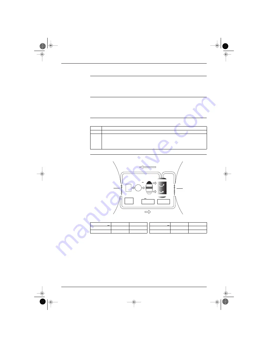
Inverter principle
To regulate the capacity, a frequency control is needed. The inverter makes it possible to vary the rotation
speed of the compressor. The following table explains the conversion principle:
Drawing of inverter
The following drawing shows a schematic view of the inverter principle:
Phase
Description
1
The single phase power supply in AC is converted into DC.
2
The single phase power supply DC is converted into a three phase shopped DC voltage with a
variable frequency.
When the frequency increases, the rotation speed of the compressor increases resulting in an
increased refrigerant circulation. This leads to a higher amount of the heat exchange per unit.
When the frequency decreases, the rotation speed of the compressor decreases resulting in a
decreased refrigerant circulation. This leads to a lower amount of the heat exchange per unit.
Min. frequency
A
H type
J type
Max. frequency
B
H type
J type
Cooling
36
34
Cooling
94
98
Heating
36
34
Heating
94
98
50 Hz
60 Hz
Refrigerant circulation rate (high)
Amount of heat
exchanged (large)
Amount of heat
exchanged (small)
AC
po
w
er
freq=cte
max. freq.=
A
Hz
DC
po
w
er
Amount of heat
exchanged (large)
Amount of heat
exchanged (small)
high f
low f
min. freq.=
B
Hz
freq=variable
capacity=
variable
Refrigerant circulation rate (low)
high speed
low speed
(RL003)
Si-86.book Page 13 Friday, June 23, 2000 10:26 AM


