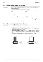
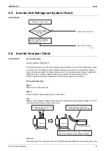
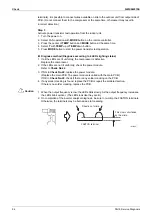
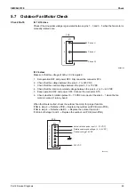
background image

SiMX042215E

Check

Part 6 Service Diagnosis

91

Note

5.2  Indoor Fan Motor Connector Check

Check No.03

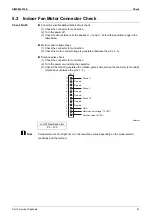
Fan motor wire breakdown/short circuit check
(1) Check the connector for connection.
(2) Turn the power off.
(3) Check if each resistance at the phases U - V and V - W is within specified range in the 

table below.

Motor control voltage check
(1) Check the connector for connection.
(2) Check the motor control voltage is generated (between the pins 2 - 3).

Rotation pulse check
(1) Check the connector for connection.
(2) Turn the power on and stop the operation.
(3) Check if the Hall IC generates the rotation pulse 4 times when the fan motor is manually 

rotated once (between the pins 1 - 3).

R6000090

A measurement error might occur in the resistance value depending on the measurement 
conditions and the method.

U-V-W Resistance (

)

90 ~ 100

12

11

10

9

8

7

6

5

4

3

2

1

Phase U

Free pin

Free pin

Free pin

Free pin

Free pin

Free pin

Phase V

Phase W

GND

Motor control voltage (15 VDC)

Rotation pulse (5 VDC)

S200

Summary of Contents for FTKM-U Series

Page 1: ...Service Manual SiMX042215E Inverter Pair Wall Mounted Type FTKM U Series Applied Models Inverter Pair Cooling Only...

Page 2: ...2 Frequency Principle 26 1 3 Airflow Direction Control 28 1 4 Fan Speed Control for Indoor Unit 29 1 5 COANDA Operation 29 1 6 Program Dry Operation 30 1 7 Thermostat Control 31 1 8 GOOD SLEEP OFF TI...

Page 3: ...e Between Indoor Unit and Outdoor Unit 68 4 10 Outdoor Unit PCB Abnormality 69 4 11 OL Activation Compressor Overload 70 4 12 Compressor Lock 72 4 13 DC Fan Lock 73 4 14 Input Overcurrent Detection 74...

Page 4: ...Field Settings 101 1 Pump Down Operation 102 2 Forced Cooling Operation 103 3 Trial Operation 104 4 Field Settings 105 4 1 When 2 Units are Installed in 1 Room 105 5 Silicone Grease on Power Transisto...

Page 5: ...042215E Introduction 1 1 Safety Cautions 2 1 1 Warnings and Cautions Regarding Safety of Workers 2 1 2 Warnings and Cautions Regarding Safety of Users 8 2 Icons Used 10 3 Revision History 11 Introduct...

Page 6: ...person in charge of maintenance and inspection This appliance is filled with R 32 Warning Do not store equipment in a room with fire sources e g naked flames gas appliances electric heaters Be sure to...

Page 7: ...nt system an excessively high pressure results causing equipment damage and injury Caution Do not repair electrical components with wet hands Working on the equipment with wet hands may cause an elect...

Page 8: ...ces including cigarette smoking should be kept at a safe distance from the site of installation repairing or removing space Before starting work the area around the equipment shall be examined to make...

Page 9: ...original specification damage to seals incorrect fitting of glands etc Ensure that the equipment is mounted securely Ensure that seals or sealing materials have not degraded such that they no longer...

Page 10: ...it with inert gas Evacuate the inert gas Purge again with inert gas Carry out cutting or brazing of the circuit The refrigerant shall be recovered into the correct recovery cylinders The system shall...

Page 11: ...re labels on the equipment stating the equipment contains R 32 Refrigerant recovery When removing refrigerant from a system either for servicing or decommissioning it is recommended to conduct trainin...

Page 12: ...ble at the connection terminals Improper connections may cause excessive heat generation or fire When wiring between the indoor and outdoor units make sure that the terminal cover does not lift off or...

Page 13: ...fire Check to see if parts and wires are mounted and connected properly and if connections at the soldered or crimped terminals are secure Improper installation and connections may cause excessive he...

Page 14: ...tion is used when there is danger that the reader through incorrect manipulation may damage equipment lose data get an unexpected result or have to restart part of a procedure Note Note Note provides...

Page 15: ...SiMX042215E Revision History Introduction 11 3 Revision History Month Year Version Revised contents 07 2022 SiMX042215E First edition...

Page 16: ...SiMX042215E 12 Part 1 General Information 1 Applicable Models 13 2 Functions 14 Part 1 General Information...

Page 17: ...SiMX042215E Applicable Models Part 1 General Information 13 1 Applicable Models Indoor Unit Outdoor Unit FTKM12UVLWZ FTKM18UVLVZ FTKM24UVLUZ RKMG12UVLWZ RKMG18UVLVZ RKMG24UVLUZ...

Page 18: ...r PM2 5 filter PM2 5 filter for streamer Mold proof air filter pre filter Wipe clean flat panel washable DEW CLEAN operation FLASH STREAMER AIR PURIFYING operation patented SMELL PROOF operation Timer...

Page 19: ...SiMX042215E Part 2 Specifications 15 1 Specifications 16 Part 2 Specifications...

Page 20: ...ing Current Rated A 0 21 0 29 Power Consumption Rated W 20 2 64 Power Factor Rated 41 6 99 1 Temperature Control Microcomputer Control Microcomputer Control Dimensions H W D mm 298 800 229 298 885 229...

Page 21: ...rrent Rated A 0 38 Power Consumption Rated W 83 Power Factor Rated 99 2 Temperature Control Microcomputer Control Dimensions H W D mm 298 885 229 Packaged Dimensions H W D mm 390 1 010 355 Weight Mass...

Page 22: ...X042215E 18 Part 3 Printed Circuit Board Connector Wiring Diagram 1 Indoor Unit 19 2 Outdoor Unit 21 2 1 12 Class 21 2 2 18 Class 22 2 3 24 Class 23 Part 3 Printed Circuit Board Connector Wiring Diagr...

Page 23: ...or swing motor vertical blade 3 S26 Connector for display signal receiver PCB A2P 4 S32 Connector for indoor heat exchanger thermistor R2T 5 S52 Connector for high voltage power supply PCB streamer un...

Page 24: ...nit 1 S27 Connector for control PCB A1P 2 BS1 Indoor unit ON OFF switch Forced cooling operation ON OFF switch Refer to page 103 for details of forced cooling operation 3 H1P LED for operation green 4...

Page 25: ...nector for compressor 4 S40 Connector for overload protector 5 S71 Connector for DC fan motor 6 S90 Connector for thermistors outdoor temperature outdoor heat exchanger discharge pipe 7 E1 Wire harnes...

Page 26: ...for compressor 4 S40 Connector for overload protector 5 S71 Connector for DC fan motor 6 S90 Connector for thermistors outdoor temperature outdoor heat exchanger discharge pipe 7 E1 Connector for ear...

Page 27: ...r for clamp PCB PCB2 4 S90 Connector for thermistors outdoor temperature outdoor heat exchanger discharge pipe 5 HL1 HN1 S Wire harness for terminal block 6 E1 E2 Wire harness for earth wire 7 U V W W...

Page 28: ...tdoor Unit SiMX042215E 24 Part 3 Printed Circuit Board Connector Wiring Diagram Clamp PCB PCB2 1 S78 Connector for main PCB PCB1 2 S79 Connector for DC fan motor 3 V160 Varistor S79 S78 3P363743 1 V16...

Page 29: ...ation 32 1 11 ECONO Operation 33 1 12 POWERFUL Operation 33 1 13 Dew Clean Operation 34 1 14 Default Set Temperature Setting 35 1 15 Other Functions 35 2 Thermistor Functions 36 3 Control Specificatio...

Page 30: ...mpressor is controlled by the following 2 parameters The load condition of the operating indoor unit The difference between the room thermistor temperature and the target temperature The target freque...

Page 31: ...ling Once the set temperature is reached the energy saving operation enables to maintain the room temperature at low power Frequency Limits The following functions regulate the maximum frequency Compr...

Page 32: ...he following table explains the auto swing process for cooling dry and fan 3 D Airflow Alternative repetition of vertical and horizontal swing motions enables uniform air conditioning of the entire ro...

Page 33: ...t the people in the room If you press SWING button during COANDA operation COANDA operation will be canceled The airflow rate can be set to any level However a low airflow rate may cause cold air to g...

Page 34: ...and the target temperature is divided into two zones Then the unit operates in an appropriate capacity for each zone to maintain the temperature and humidity at a comfortable level Thermostat turns on...

Page 35: ...ation starts the target temperature will increase gradually by 2 C in the next 2 hours to prevent excessive cooling for your pleasant sleep Not available in dry operation 1 9 SMELL PROOF Operation The...

Page 36: ...is being cleaned To stop the operation Press STREAMER button for more than 5 seconds again The icon disappears from the display The streamer will stop operating This is a type of plasma discharge comp...

Page 37: ...ty 1 12 POWERFUL Operation Outline In order to exploit the cooling capacity to full extent the air conditioner can be operated by increasing the indoor fan rotating speed and the compressor frequency...

Page 38: ...clean operation turn off the unit by pressing ON OFF button on remote controller R4003858 During dew clean operation other functions of remote controller except streamer function are not available suc...

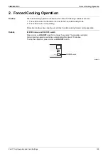
Page 39: ...eration Press once again to stop it ON OFF switch is useful when the remote controller is missing or the battery has run out The operation mode refers to the following table R4003873 Forced Cooling Op...

Page 40: ...hermistor is judged as disconnected In cooling operation the outdoor heat exchanger thermistor is used for high pressure protection 3 Outdoor Temperature Thermistor The outdoor temperature thermistor...

Page 41: ...r limit frequency among the frequency upper limits of the following functions Compressor protection input current discharge pipe temperature freeze up protection 3 Determine lower limit frequency The...

Page 42: ...oes not change for more than a certain fixed time the frequency is adjusted according to D value When D is low the frequency is lowered When D is high the frequency is increased 3 Frequency control wh...

Page 43: ...ncy is set to keep the discharge pipe temperature from rising further Details A D E F B C R13528 Hz Frequency sec Time 12 class 18 class 24 class A Hz 44 40 24 B Hz 80 60 52 C Hz 110 79 68 D seconds 1...

Page 44: ...The upper limit of the compressor frequency is defined as operation frequency 2 Hz After this the output frequency is lowered by 2 Hz every second until it reaches the keep zone Keep zone The present...

Page 45: ...ssure difference during cooling operation with low outdoor temperature When the pressure difference is low the rotation speed of the outdoor fan is reduced When the pressure difference is high the rot...

Page 46: ...rol when the frequency changes 3 Electronic expansion valve control when the discharge pipe temperature is abnormally high 4 Electronic expansion valve control when the discharge pipe thermistor is di...

Page 47: ...pansion valve is changed according to the frequency shift 3 9 6 High Discharge Pipe Temperature Control When the compressor is operating if the discharge pipe temperature exceeds a certain value the e...

Page 48: ...If the disconnection is detected repeatedly the system is shut down When the compressor runs for 60 minutes without any error the error counter is reset Details Determining thermistor disconnection W...

Page 49: ...Refrigerant shortage is detected if the power consumption is below the specified value and the frequency is higher than the specified frequency When refrigerant is insufficient the power consumption...

Page 50: ...SiMX042215E 46 Part 5 Remote Controller 1 Applicable Remote Controller 47 2 ARC484B41 48 Part 5 Remote Controller...

Page 51: ...SiMX042215E Applicable Remote Controller Part 5 Remote Controller 47 1 Applicable Remote Controller Model Name Remote Controller Reference Page FTKM12UVLWZ ARC484B41 48 FTKM18UVLVZ FTKM24UVLUZ...

Page 52: ...quieter In indoor unit quiet operation operation sound becomes weak The airflow rate also decreases In DRY operation the airflow rate setting is not available POWERFUL 1 button Starts POWERFUL operati...

Page 53: ...tion Compressor Overload 70 4 12 Compressor Lock 72 4 13 DC Fan Lock 73 4 14 Input Overcurrent Detection 74 4 15 Discharge Pipe Temperature Control 75 4 16 High Pressure Control in Cooling 77 4 17 Sys...

Page 54: ...SiMX042215E 50 Part 6 Service Diagnosis 5 9 Discharge Pressure Check 96 5 10 Outdoor Fan System Check 97 5 11 Main Circuit Short Check 97 5 12 Power Module Check 99...

Page 55: ...k the power supply A power failure of 2 to 10 cycles can stop air conditioner operation Operation lamp OFF Check the outdoor temperature Cooling operation is not available when the outdoor temperature...

Page 56: ...door or outdoor unit is activated or when the thermistor malfunctions 2 When a signal transmission error occurs between the indoor and outdoor units In either case conduct the diagnostic procedure des...

Page 57: ...old TIMER CANCEL button down for 5 seconds When the remote controller is left untouched for 60 seconds it also returns to the normal mode 3 Not all the error codes are displayed When you cannot find t...

Page 58: ...onsecutive beeps or the long beep 3 Diagnose by the sound Beep The left side number does not correspond with the error code Two consecutive beeps The left side number corresponds with the error code b...

Page 59: ...orresponds with the error code but the right side number does not Long beep Both the left side and right side numbers correspond with the error code 7 Determine the error code The numbers indicated wh...

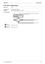
Page 60: ...ure thermistor or related abnormality 61 Outdoor Unit E1 Outdoor unit PCB abnormality 69 E5 OL activation compressor overload 70 E6 Compressor lock 72 E7 DC fan lock 73 E8 Input overcurrent detection...

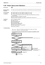
Page 61: ...the connection of connectors wire harness Correct the connection OK Check the power supply voltage Start operation Voltage as rated Error repeats Check the power supply voltage Start operation Voltage...

Page 62: ...he indoor heat exchanger Defective indoor heat exchanger thermistor Defective indoor unit PCB Troubleshooting Check No 01 Refer to P 90 NO NO NO Check No 01 Check the indoor heat exchanger thermistor...

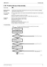
Page 63: ...operation The fan motor stops its rotation within 5 seconds after the operation starts Error Decision Conditions The detected rotation speed does not reach the demanded rotation speed of the target t...

Page 64: ...sconnect the connector and then reconnect it Foreign matters in or around the fan Is the rotation pulse generated Rotate the fan by hand Turn the power on again Check the fan motor for breakdown or sh...

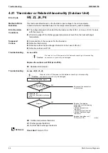
Page 65: ...s with the power on Supposed Causes Disconnection of connector Defective thermistor s Defective indoor unit PCB Troubleshooting C4 Indoor heat exchanger thermistor C9 Room temperature thermistor Check...

Page 66: ...ns Refrigerant shortage detection I The following conditions continue for 7 minutes Input current input voltage A output frequency B Output frequency C Refrigerant shortage detection II electronic exp...

Page 67: ...stor Check for refrigerant shortage Change for a specified amount of fresh refrigerant Reconnect the thermistor s Open the stop valve Repair the pipe flare or replace the union Check if any harnesses...

Page 68: ...age detected by the DC voltage detection circuit is below 150 200 V 12 18 class or 180 196 V 24 class The compressor stops if the error occurs and restarts automatically after 3 minute standby Over vo...

Page 69: ...r supply voltage Check the connection of the compressor harness Turn on the power Disturbance factors Noise Power supply distortion Precaution before turning on the power again Make sure the power has...

Page 70: ...normal Error Decision Conditions The data sent from the outdoor unit cannot be received normally or the content of the data is abnormal Supposed Causes Power supply voltage out of specification Reduct...

Page 71: ...unit and the outdoor unit Replace the outdoor unit PCB main PCB Replace the connection wires between the indoor unit and outdoor unit Is LED A blinking Properly insulated Is there any disturbance Is...

Page 72: ...g models interconnected Wrong wiring of connecting wires Wrong indoor unit PCB or outdoor unit PCB mounted Defective indoor unit PCB Defective outdoor unit PCB Troubleshooting R23289 Caution NO YES YE...

Page 73: ...The zero cross signal is not detected Supposed Causes Defective outdoor unit PCB Noise Momentary drop of voltage Momentary power failure Troubleshooting Caution Be sure to turn off the power switch b...

Page 74: ...he system is shut down Reset condition Continuous run for about 60 minutes without any other error Supposed Causes Disconnection of discharge pipe thermistor Defective discharge pipe thermistor Discon...

Page 75: ...electronic expansion valve or the coil Discharge pipe thermistor disconnected Check No 12 Check the electronic expansion valve Replace the OL Q1L Replace the OL harness Connect the connector S40 prope...

Page 76: ...d W Caution NO YES NO NO YES NO YES Check No 15 Check with the inverter analyzer Turn off the power and reconnect the harnesses Turn on the power again and restart the system Precaution before turning...

Page 77: ...nnection of the fan motor Foreign matter stuck in the fan Defective fan motor Defective outdoor unit PCB Troubleshooting Check No 16 Refer to P 95 R20416 Caution YES YES NO YES NO NO YES NO Turn on th...

Page 78: ...eck No 18 Refer to P 96 Caution Be sure to turn off the power switch before connecting or disconnecting connectors or parts may be damaged An input overcurrent may result from wrong internal wiring If...

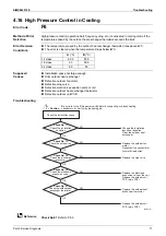
Page 79: ...rror 12 class R6000880 18 class 24 class Supposed Causes Defective discharge pipe thermistor Defective outdoor heat exchanger thermistor or outdoor temperature thermistor Defective electronic expansio...

Page 80: ...Outdoor temperature thermistor Refrigerant shortage Water mixed Stop valve Check No 01 Check the thermistors Check No 14 Check the refrigerant line Check No 12 Check the electronic expansion valve Rep...

Page 81: ...stor Defective outdoor unit PCB Troubleshooting Check No 01 Refer to P 90 A C B C 12 class 62 5 55 5 18 class 63 55 5 24 class 60 55 R20418 Caution Replace the outdoor fan motor Reconnect the connecto...

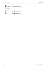
Page 82: ...Troubleshooting SiMX042215E 78 Part 6 Service Diagnosis Reference Reference Reference Reference Check No 12 Refer to P 92 Check No 17 Refer to P 96 Check No 18 Refer to P 96 Check No 19 Refer to P 97...

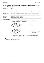
Page 83: ...auses Abnormal operation due to air intrusion Defective discharge pipe thermistor Troubleshooting Check No 01 Refer to P 90 YES R23655 NO OK NG Caution Replace the outdoor unit Replace both the discha...

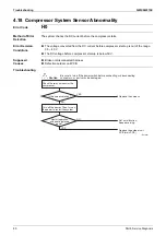
Page 84: ...tage before compressor start up is below 50 V Supposed Causes Broken or disconnected harness Defective outdoor unit PCB Troubleshooting Caution Be sure to turn off the power switch before connecting o...

Page 85: ...d Causes Power supply voltage out of specification Disconnection of the compressor harness Defective compressor Defective outdoor unit PCB Start up failure caused by the closed stop valve Input voltag...

Page 86: ...n on the power Check the capacitor voltage Turn off the power Disconnect the harnesses U V and W Electrical components or compressor harnesses connected as specified Replace the outdoor unit PCB main...

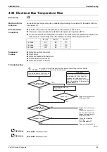
Page 87: ...compressor running frequency and the input current Error Decision Conditions If the error repeats the system is shut down Reset condition Continuous run for about 60 minutes without any other error Su...

Page 88: ...ase of J3 error Defective outdoor unit PCB Troubleshooting In case of P4 Replace the outdoor unit PCB main PCB P4 Radiation fin thermistor Troubleshooting In case of H9 J3 J6 H9 Outdoor temperature th...

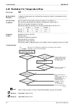
Page 89: ...ve outdoor unit PCB Troubleshooting Check No 17 Refer to P 96 Check No 19 Refer to P 97 A C B C C C 12 class 94 82 87 18 class 95 5 80 85 24 class 100 64 91 Caution WARNING To cool the electrical comp...

Page 90: ...ation fin after replacing the outdoor unit PCB Troubleshooting Refer to Silicone Grease on Power Transistor Diode Bridge on page 106 for details Check No 17 Refer to P 96 Check No 19 Refer to P 97 12...

Page 91: ...ion Defective compressor Troubleshooting R24911 Caution NO YES NO YES An output overcurrent may result from wrong internal wiring If the system is interrupted by an output overcurrent after the wires...

Page 92: ...harnesses Turn on the power again and start operation Check the power supply voltage Check the power module Correct the power supply Replace the compressor Correct the power supply or replace the out...

Page 93: ...oltage detection OL Activation compressor overload Troubleshooting Refer to U2 on P 64 Refer to E5 on P 70 Caution NO YES Check item U2 Check item E5 Is the error code E5 Be sure to turn off the power...

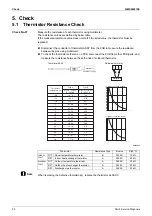
Page 94: ...tive thermistor s replace the thermistor as ASSY Thermistor Resistance Type B value R 25 C Indoor Unit R1T Room temperature thermistor B 3435 K 10 k R2T Indoor heat exchanger thermistor A 3950 K 20 k...

Page 95: ...control voltage is generated between the pins 2 3 Rotation pulse check 1 Check the connector for connection 2 Turn the power on and stop the operation 3 Check if the Hall IC generates the rotation pul...

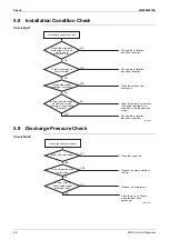
Page 96: ...nector is correctly connected to the PCB 2 Turn the power off and on again and check if the EV generates a latching sound 3 If the EV does not generate a latching sound in the step 2 above disconnect...

Page 97: ...ethod Step 1 Be sure to turn the power off Step 2 Install an inverter analyzer instead of a compressor Note Make sure the charged voltage of the built in smoothing electrolytic capacitor drops to 10 V...

Page 98: ...1 If all the LEDs are lit uniformly the compressor is defective Replace the compressor 2 If the LEDs are not lit uniformly check the power module Refer to Check No 22 3 If NG in Check No 22 replace t...

Page 99: ...motor If OK in both steps 2 and 4 Replace the outdoor unit PCB main PCB 1 Set operation OFF and power OFF Disconnect the connector S70 2 Check that the voltage between the pins 4 7 is 320 VDC 3 Check...

Page 100: ...heat exchanger very dirty Change the installation location or direction Change the installation location or direction Clean the outdoor heat exchanger Change the installation location or direction Ch...

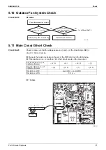
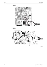
Page 101: ...ing to the table below If the resistance is or less than 1 k short circuit occurs on the main circuit 12 class R6000751 R21195 YES NO NO YES Outdoor fan system is functioning Check the outdoor fan sys...

Page 102: ...Check SiMX042215E 98 Part 6 Service Diagnosis 18 class R6000724 24 class 1 2 3 4 Multimeter R23458 Multimeter 1 2 3 4...

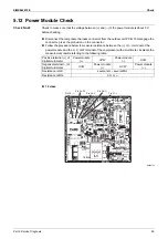
Page 103: ...the connector Follow the procedure below to measure resistance between the or terminal of the power module and the U V or W terminal of the compressor with a multimeter Evaluate the measurement result...

Page 104: ...Check SiMX042215E 100 Part 6 Service Diagnosis 18 class R6000725 24 class R6000303 Pin 24 Pin 23 U Pin 22 V Pin 21 W Pin 20 Pin 24 Pin 23 U Pin 22 V Pin 21 W Pin 20...

Page 105: ...ngs 101 1 Pump Down Operation 102 2 Forced Cooling Operation 103 3 Trial Operation 104 4 Field Settings 105 4 1 When 2 Units are Installed in 1 Room 105 5 Silicone Grease on Power Transistor Diode Bri...

Page 106: ...the valve caps from the liquid stop valve and the gas stop valve 2 Carry out forced cooling operation 3 After 5 to 10 minutes close the liquid stop valve with a hexagonal wrench 4 After 2 to 3 minute...

Page 107: ...l and not in the 3 minute standby mode 2 The outdoor unit is not operating Protection functions have priority over all other functions during forced cooling operation Details With indoor unit ON OFF s...

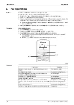
Page 108: ...m 2 Press both of TEMP button and MODE button at the same time 3 Press TEMP button select T and press MODE button for confirmation Trial operation will stop automatically after about 30 minutes To sto...

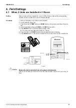
Page 109: ...mote controller at the same time 4 Select A address setting with TEMP up or TEMP down button 5 Press MODE button to enter the address setting mode The indoor unit operation lamp blinks for 1 minute 6...

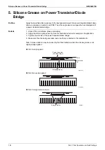
Page 110: ...ode bridge Details 1 Wipe off the old silicone grease completely 2 Apply the silicone grease evenly See the illustrations below for examples of application 3 Tighten the screws of the power transistor...

Page 111: ...SiMX042215E Part 8 Appendix 107 1 Piping Diagrams 108 1 1 Indoor Unit 108 1 2 Outdoor Unit 109 2 Wiring Diagrams 110 2 1 Indoor Unit 110 2 2 Outdoor Unit 111 3 Operation Limit 114 Part 8 Appendix...

Page 112: ...Piping Diagrams SiMX042215E 108 Part 8 Appendix 1 Piping Diagrams 1 1 Indoor Unit FTKM12UVLWZ FTKM18UVLVZ FTKM24UVLUZ 4D086364T 4D113909J 4D108592N...

Page 113: ...SiMX042215E Piping Diagrams Part 8 Appendix 109 1 2 Outdoor Unit RKMG12UVLWZ RKMG18UVLVZ RKMG24UVLUZ 4D137518 4D113913D 4D102415F...

Page 114: ...15E 110 Part 8 Appendix Note 2 Wiring Diagrams 2 1 Indoor Unit FTKM12UVLWZ FTKM18UVLVZ FTKM24UVLUZ A1P Control PCB A2P Display signal receiver PCB Refer to page 19 for Printed Circuit Board Connector...

Page 115: ...SiMX042215E Wiring Diagrams Part 8 Appendix 111 Note s 2 2 Outdoor Unit RKMG12UVLWZ PCB 1 Main PCB Refer to page 21 for Printed Circuit Board Connector Wiring Diagram 3D141997...

Page 116: ...Wiring Diagrams SiMX042215E 112 Part 8 Appendix Note s RKMG18UVLVZ PCB 1 Main PCB Refer to page 22 for Printed Circuit Board Connector Wiring Diagram 3D128989A...

Page 117: ...SiMX042215E Wiring Diagrams Part 8 Appendix 113 Note s RKMG24UVLUZ PCB 1 Main PCB PCB 2 Clamp PCB Refer to page 23 for Printed Circuit Board Connector Wiring Diagram 3D121872...

Page 118: ...Operation Limit SiMX042215E 114 Part 8 Appendix 3 Operation Limit RKMG12UVLWZ RKMG18UVLVZ RKMG24UVLUZ 4D142785...

Page 119: ...ct will be used This statement does not purport to exclude restrict or modify the application of any local legislation z z Ask a qualified installer or contractor to install this product Do not try to...

Reviews: