Troubleshooting
SiBE04-302
100
Service Diagnosis
4.9
Input Over Current Detection
Remote
Controller
Display
E8
Method of
Malfunction
Detection
An input over-current is detected by checking the input current value being detected by CT with
the compressor running.
Malfunction
Decision
Conditions
The following CT input with the compressor running continues for 2.5 seconds.
Cooling: Above 11A, Heating: Above 13A
Supposed
Causes
Over-current due to compressor failure
Over-current due to defective power transistor
Over-current due to defective outdoor unit PCB
Error detection due to outdoor unit PCB
Over-current due to short-circuit
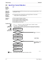
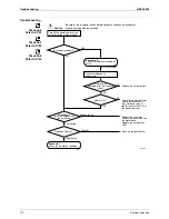
Troubleshooting
Check No.7
Refer to P.123
Check No.8
Refer to P.124
Note:
If the model doesn’t have SPM, replace the outdoor unit PCB.
Replace the outdoor unit
PCB.
∗
Inverter checker
Part No.: 1225477
Correct the power supply or
replace the SPM.
(Replace the outdoor unit
PCB.)
(R2952)
Caution
Be sure to turn off power switch before connect or disconnect connector,
or parts damage may be occurred.
Input current flowing
above its stop level?
NO
YES
Any LED off?
YES
NO
Check with the inverter checker (
∗
).
Turn off the power, and reconnect
the harnesses. Turn on the power
again and get restarted.
Turn off the power and disconnect
the harnesses U, V and W.
Get restarted and measure the
input current.
Check No. 8
Check the discharge pressure.
Check No. 7
Check the installation condition.
∗
An input over-current may result from wrong internal wiring. If the wires have been disconnected and
reconnected for part replacement, for example, and the system is interrupted by an input over-current,
take the following procedure.
Summary of Contents for FTKS25BVMB
Page 17: ...Functions SiBE04 302 8 List of Function...
Page 31: ...Specifications SiBE04 302 22 Specifications...
Page 137: ...Check SiBE04 302 128 Service Diagnosis...
Page 172: ...SiBE04 302 Outdoor Unit Removal Procedure 163 4 Remove the fan motor Step Procedure Points...
Page 184: ...SiBE04 302 Others 175 Part 8 Others 1 Others 176 1 1 Explanation 176 1 2 Jumper Settings 177...
Page 195: ...Wiring Diagrams SiBE04 302 186 Appendix...
Page 199: ...SiBE04 302 iv Index...


