background image

English

9

Englis

h

Indoor Unit Installation

Wiring diagram

CAUTION
Note that operation will restart automatically if the 
main power supply is turned off and then back on again.
HIGH VOLTAGE – be sure to discharge the capacitor completely before repair work.
Risk of failure or water leakage!
Do not wash the inside of the air conditioner by yourself.

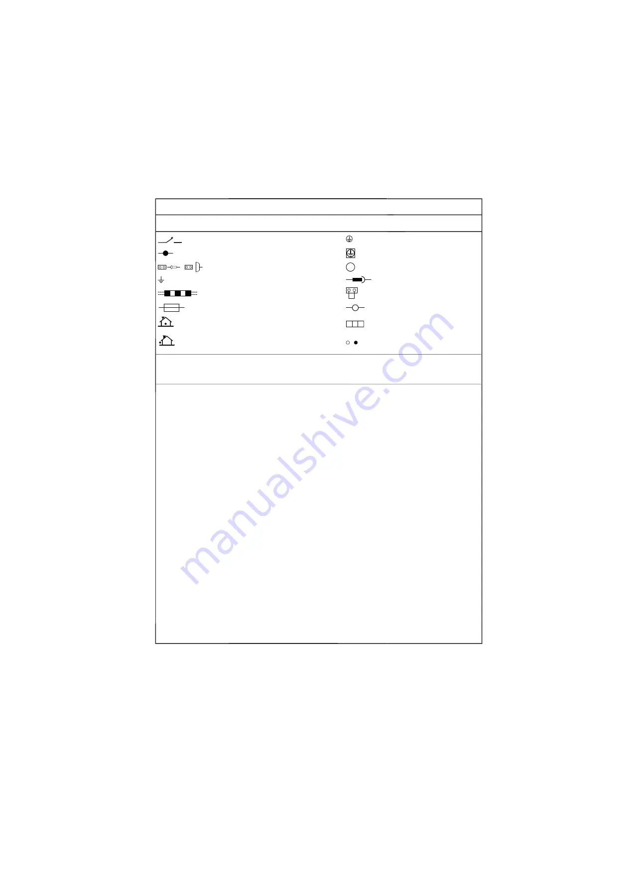
Unified Wiring Diagram Legend

For applied parts and numbering refer to the wiring diagram sticker supplied on the unit. Part numbering is realized by Arabic numbers in ascending order for each part and

 is represented in the overview below by symbol “*” in the part code.

:

CIRCUIT BREAKER

:

PROTECTIVE EARTH

:

CONNECTION

:

PROTECTIVE EARTH (SCREW)

,

:

CONNECTOR

:

RECTIFIER

:

EARTH

:

RELAY CONNECTOR

:

FIELD WIRING

:

SHORT CIRCUIT CONNECTOR

:

FUSE

:

TERMINAL

䣋䣐䣆䣑䣑䣔

:

INDOOR UNIT

:

TERMINAL STRIP

䣑䣗䣖䣆䣑䣑䣔

:

OUTDOOR UNIT

:

WIRE CLAMP

BLK

:

BLACK

GRN

:

GREEN

PNK

:

PINK

WHT

:

WHITE

BLU

:

BLUE

GRY

:

GREY

PRP, PPL

:

PURPLE

YLW

:

YELLOW

BRN

:

BROWN

ORG

:

ORANGE

RED

:

RED

A*P

:

PRINTED CIRCUIT BOARD

PS

:

SWITCHING POWER SUPPLY

BS*

:

PUSH BUTTON ON / OFF, OPERATION SWITCH

PTC*

:

THERMISTOR PTC

BZ, H*O

:

BUZZER

Q*

:

INSULATED GATE BIPOLAR TRANSISTOR (IGBT)

C*

:

CAPACITOR

Q*DI

:

EARTH LEAK CIRCUIT BREAKER

AC*, CN*, E*, HA*, HE, HL*, HN*, 
HR*, MR*_A, MR*_B, S*, U, V, 
W, X*A

:

CONNECTION, CONNECTOR

Q*L

:

OVERLOAD PROTECTOR

D*, V*D

:

DIODE

Q*M

:

THERMO SWITCH

DB*

:

DIODE BRIDGE

R*

:

RESISTOR

DS*

:

DIP SWITCH

R*T

:

THERMISTOR

E*H

:

HEATER

RC

:

RECEIVER

F*U, FU* 

(FOR CHARACTERISTICS 

REFER TO PCB INSIDE YOUR UNIT)

:

FUSE S*C

:

LIMIT 

SWITCH

FG*

:

CONNECTOR (FRAME GROUND)

S*L

:

FLOAT SWITCH

H*

:

HARNESS

S*NPH

:

PRESSURE SENSOR (HIGH)

H*P, LED*, V*L

:

PILOT LAMP, LIGHT EMITTING DIODE

S*NPL

:

PRESSURE SENSOR (LOW)

HAP

:

LIGHT EMITTING DIODE (SERVICE MONITOR GREEN)

S*PH, HPS*

:

PRESSURE SWITCH (HIGH)

HIGH VOLTAGE

:

HIGH VOLTAGE

S*PL

:

PRESSURE SWITCH (LOW)

IES

:

INTELLIGENT EYE SENSOR

S*T

:

THERMOSTAT

IPM*

:

INTELLIGENT POWER MODULE

S*W, SW*

:

OPERATION SWITCH

K*R, KCR, KFR, KHuR

:

MAGNETIC RELAY

SA*

:

SURGE ARRESTOR

L

:

LIVE

SR*, WLU

:

SIGNAL RECEIVER

L*

:

COIL

SS*

:

SELECTOR SWITCH

L*R

:

REACTOR

SHEET METAL

:

TERMINAL STRIP FIXED PLATE

M*

:

STEPPER MOTOR

T*R

:

TRANSFORMER

M*C

:

COMPRESSOR MOTOR

TC, TRC

:

TRANSMITTER

M*F

:

FAN MOTOR

V*, R*V

:

VARISTOR

M*P

:

DRAIN PUMP MOTOR

V*R

:

DIODE BRIDGE

M*S

:

SWING MOTOR

WRC

:

WIRELESS REMOTE CONTROLLER

MR*, MRCW*, MRM*, MRN* 

:

MAGNETIC RELAY

X*

:

TERMINAL

N

:

:

NEUTRAL

X*M

:

TERMINAL STRIP (BLOCK)

n = *

NUMBER OF PASSES THROUGH FERRITE CORE

Y*E

:

ELECTRONIC EXPANSION VALVE COIL

PAM

:

PULSE-AMPLITUDE MODULATION

Y*R, Y*S

:

REVERSING SOLENOID VALVE COIL

PCB*

:

PRINTED CIRCUIT BOARD

Z*C

:

FERRITE CORE

PM*

:

POWER MODULE

ZF, Z*F

:

NOISE FILTER

CIRCUIT BREAKER

Summary of Contents for FTXL25J2V1B

Page 1: ...INSTALLATION MANUAL R410A Split Series Models FTXL25J2V1B FTXL35J2V1B ATXL25J2V1B ATXL35J2V1B DAIKIN...

Page 2: ...12 gitt i henhold til bestemmelsene i 13 noudattaen m r yksi 14 za dodr en ustanoven p edpisu 15 prema odredbama 16 k veti a z 17 zgodnie z postanowieniami Dyrektyw 18 n urma prevederilor 19 ob upo t...

Page 3: ...may cause overheating electric shocks or fire Make sure that all wiring is secured the specified wires are used and that there is no strain on the terminal connections or wires Improper connections o...

Page 4: ...ite where remote controller signals are properly received by the indoor unit within 7 metres CAUTION Do not install the air conditioner at any place where there is a danger of flammable gas leakage In...

Page 5: ...d push down on the hooks with the fingers of your other hand When there is no work space because the unit is close to ceiling CAUTION Be sure to wear protection gloves Place both hands under the centr...

Page 6: ...panel 50mm or more from walls on both sides Air filters Titanium apatite deodorizing filter 2 Air filter Titanium apatite deodorizing filter Filter frame Tab Service lid Opening service lid The servi...

Page 7: ...the wall with screws Recommended mounting plate retention spots and Dimensions Use tape measure as shown Position the end of a tape measure at Keep here the piece cut out from the unit for piping Liqu...

Page 8: ...pes keep the following precautions in mind Abnormal sound may be generated if improper work is conducted 1 Do not strongly press the refrigerant pipes onto the bottom frame 2 Do not strongly press the...

Page 9: ...the back of the indoor unit Pull them through the front side Bend the ends of tie wires upward for easier work in advance If the interconnecting wire ends are to be stripped first bundle wire ends wi...

Page 10: ...to remove the drain hose 2 Reattach the insulation fixing screw on the right as it was Forgetting to attach this may cause water leakages 3 Remove the drain plug on the left side and attach it to the...

Page 11: ...IRCUIT BREAKER AC CN E HA HE HL HN HR MR _A MR _B S U V W X A CONNECTION CONNECTOR Q L OVERLOAD PROTECTOR D V D DIODE Q M THERMOSWITCH DB DIODEBRIDGE R RESISTOR DS DIP SWITCH R T THERMISTOR E H HEATER...

Page 12: ...e 5 When connecting to a wired remote controller If work space is available on the right side of the indoor unit the work can be performed with the electrical component box attached Omit the steps inv...

Page 13: ...ct into the indoor unit electrical component box 2 Route the connection cord as shown in Figure 3 5 8 Install the indoor unit electrical component box in its original position 1 Install the flap 2 Ins...

Page 14: ...rly made WARNING Do not use mineral oil on flared part Prevent mineral oil from getting into the system as this would reduce the lifetime of the units Never use piping which has been used for previous...

Page 15: ...Refrigerant gas pipe s surface temperature reaches 110 C max Choose heat insulation materials that will withstand this temperature 2 Be sure to insulate both the gas and liquid piping and to provide i...

Page 16: ...cessary power consumption If the circuit breaker trips to shut off the power to the air conditioner the system will restore the original operation mode when the circuit breaker is opened again 2 Test...

Page 17: ......

Page 18: ......

Page 19: ......

Page 20: ...3P377527 2D 2017 02 Copyright 2014 Daikin...

Reviews: