background image

English

10

6.

Wiring.

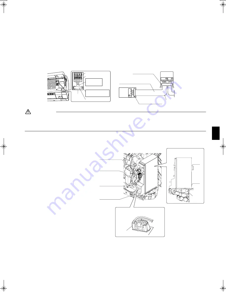
1) Strip wire ends (15mm).
2) Match wire colours with terminal numbers on indoor and outdoor unit’s terminal blocks and firmly screw wires to the 

corresponding terminals.

3) Connect the earth wires to the corresponding terminals.
4) Pull wires to make sure that they are securely latched up, then retain wires with wire retainer.
5) In case of connecting to an adapter system. Run the remote control cable and attach the S21. 

(Refer to 

7. Connecting to the HA system

.)

6) Shape the wires so that the service lid fits securely, then close service lid.

WARNING

1) Do not use tapped wires, strand wires, extensioncords, or starburst connections, as they may cause overheating, electrical 

shock, or fire.

2) Do not use locally purchased electrical parts inside the product. (Do not branch the power for the drain pump, etc., from the 

terminal block.) Doing so may cause electric shock or fire.

7.

Connecting to the HA system.

1) Remove the front grille. (3 screws) 
2) Remove the decelerator assembly parts. 

(1 screw)
2-1) Remove the decelerator assembly 

part screws. (See Fig. 1)

2-2) Remove the decelerator assembly 

part connector. Remove by pressing 
on the tabs on the bottom of the 
connector. 
(See the tab position diagram 1)

3) Remove the electric parts box. 

(1 screw, 2 tabs)
3-1) Remove the electric parts box fixing 

screw.

3-2) Pull the electric parts box toward 

you and discharge the tab2.

Shape wires so 
that the service 
lid will fit securely.

Terminal block

Electrical component box

Wire retainer

Firmly secure wire retainer 
so that wires sustain no 
external stress.

Use the 
specified 
wire type.

1
2
3

1 2 3

L N

When wire length exceeds 
10m, use 2.0mm diameter wires.

H05VV

Firmly fix the wires with 
the terminal screws.

Outdoor unit

Indoor 
unit

Firmly fix the wires with 
the terminal screws.

Fig. 1

Decelerator assembly 
part fixing screw

Anti-drip cover

Electric parts box 
fixing screw

Anti-drip cover 
fixing screw

Position of tabs on the decelerator 
assembly part connector

Location of the tabs 
on the electric parts box

Tab

Tab 2

Tab 1

Buzzer

01_EN_3P177302-1.fm  Page 10  Tuesday, May 30, 2006  9:36 AM

Summary of Contents for FTXR28EV1B

Page 1: ...ies Montaj kýlavuzlarý R410A Split serisi Installationsanleitung Split Baureihe R410A Manuel d installation Série split R410A Montagehandleiding R410A Split systeem Manual de instalación Serie Split R410A Manuale d installazione Serie Multiambienti R410A Εγχειρßδιο εγκατÜστασηò διαιροýìενηò σειρÜò R410A Manual de Instalação Série split R410A Рóêоводство по монтажó Серия R410A с раздельной óстановê...

Page 2: ...n TCF 015 74736 KRQ EMC97 4957 Daikin TCF 015 74736 KRQ EMC97 4957 Daikin TCF 015 74736 KRQ EMC97 4957 Daikin TCF 015 74736 KRQ EMC97 4957 Daikin TCF 015 74736 KRQ EMC97 4957 Daikin TCF 015 74736 KRQ EMC97 4957 Daikin TCF 015 74736 KRQ EMC97 4957 Daikin TCF 015 74736 KRQ EMC97 4957 Daikin TCF 015 74736 KRQ EMC97 4957 Daikin TCF 015 74736 KRQ EMC97 4957 Daikin TCF 015 74736 KRQ EMC97 4957 Daikin TC...

Page 3: ...e cables so that they do not put undue force on the electrical covers or panels Install covers over the wires Incomplete cover installation may cause terminal overheating electrical shock or fire If any refrigerant has leaked out during the installation work ventilate the room The refrigerant produces a toxic gas if exposed to flames After all installation is complete check to make sure that no re...

Page 4: ...tallation work When embedding humidifying hose 1 Cannot be installed to the existing embedded piping Embedding work is separately necessary The length of the humidifying hose is marked on the hose packing material 1 Use an extension hose sold separately when extending the humidifying hose 2 The length of the humidifying hose needs to be set to ensure humidifying capacity Cut off any excess hose Us...

Page 5: ... to the humidifying hose as much as possible If it is difficult to lay the humidifying hose cut it lay it and connect it using the joint or elbow included with the outdoor unit Cut thermal insulation pipe to an appropriate length and wrap it with tape making sure that no gap is left in the insulation pipe s cut line 30mm or more from ceiling 50mm or more from walls on both sides Screws Field suppl...

Page 6: ... on both sides of the front panel 2 Removing and installing the upper panel Removal method 1 Remove the front panel and air filter 2 Hold and pull forward 2 tabs on both sides to discharge them discharge the center tab and then lift up the upper panel Installation method 1 Push in the upper panel along the guide on the top of the front grille and insert the 3 tabs into the slots on the front grill...

Page 7: ...e left air filter to its original position and close the front panel 5 Installing the titanium apatite photocatalytic air purifying filter and deodorizing filter for streamer 1 Open the front panel to pull out the air filter 2 Attach the titanium apatite photocatalytic air purifying filter 3 Attach the deodorizing filter for streamer 4 Replace the air filter to its original position and close the ...

Page 8: ... wireless remote controllers can be set for different addresses 1 Remove the front grille 3 screws 2 Cut the address jumper JA See Fig 1 3 Remove the remote controller lid and cut the address jumper J4 See Fig 2 Attachment on the right side factory default Drain hose Attachment on the left side The drain hose is on the back of the unit Front side of unit Drain hose Drain hose attachment position R...

Page 9: ...the inter unit wiring from the back of the indoor unit to the front It is easier to pull out if bending up the wire edge in advance 3 To connect the inter unit wiring after hooking the unit onto the mounting plate connect the inter unit wiring as shown in the figure at right A A A Bolt size M10 165 285 145 45 14 5 305 44 5 260 5 44 5 37 150 100 385 385 170 302 5 343 5 343 5 393 5 15 890 12 120 120...

Page 10: ...4 Connect the pipes If it is difficult to do remove the front panel first 5 Wrap the insulation on the piping with insulation tape If you are not replacing the drain hose store it in the location shown below 4 3 Left back piping Drain hose Gas pipe Liquid pipe Inter unit wiring Humidifying hose Insulation tape Piping bundle diagram Cut out the piping through hole Install with a downward slope Cut ...

Page 11: ...be pulled out of drain pipe Left side left back or left bottom piping Insert as far as possible so that there are no gaps Cut the cuff at this part Left back piping It is easier to connect the hose with the front grille removed Cuff Humidifying hose Connect the cuff side of the humidifying hose to the indoor unit duct The protrusion of the humidifying hose from the wall hole is about 100mm If it i...

Page 12: ...stem 1 Remove the front grille 3 screws 2 Remove the decelerator assembly parts 1 screw 2 1 Remove the decelerator assembly part screws See Fig 1 2 2 Remove the decelerator assembly part connector Remove by pressing on the tabs on the bottom of the connector See the tab position diagram 1 3 Remove the electric parts box 1 screw 2 tabs 3 1 Remove the electric parts box fixing screw 3 2 Pull the ele...

Page 13: ...to the drain hose attached to the indoor unit as with embedded piping work use any commercially available drain socket nominal diameter 13mm as a joint 9 Improving installation strength We recommend screwing the indoor unit onto a mounting plate in order to improve the installation strength 1 Remove the front grille 2 Screw in the indoor unit with fixing screws 3 Attach the front grille Tab 3 Elec...

Page 14: ...Default is no setting 4 Press SELECT button to set the humidifying hose length Pressing SELECT button changes the hose length You may set the hose length to 5 levels 3M 3 1 4M 4 1 6M 6 1 8M 8 1 10M 5 Press CLOCK button after selecting the hose length Direct the remote controller toward the main unit while operating it 6 Hold CLOCK button for more than 5 seconds The humidifying hose length setting ...

Page 15: ...or larger 2 2 Selection of copper and heat insulation materials When using commercial copper pipes and fittings observe the following 1 Insulation material Polyethylene foam Heat transfer rate 0 041 to 0 052W mK 0 035 to 0 045 kcal mh C Refrigerant gas pipe s surface temperature reaches 110 C max Choose heat insulation materials that will withstand this temperature 2 Be sure to insulate both the g...

Page 16: ...the air supply filter Noise water leakage Did you install the deodorizing filter for the streamer and the titanium apatite photocatalytic air purifying filter Noise water leakage Have you performed a gas leak test Incomplete cooling heating function No refrigerant gas leaks Incomplete cooling heating function Refrigerant gas and liquid pipes and indoor drain hose extension are thermally insulated ...

Page 17: ... 0605 HT 3P177302 1 M05B200 ...

Reviews: