12
Application Information
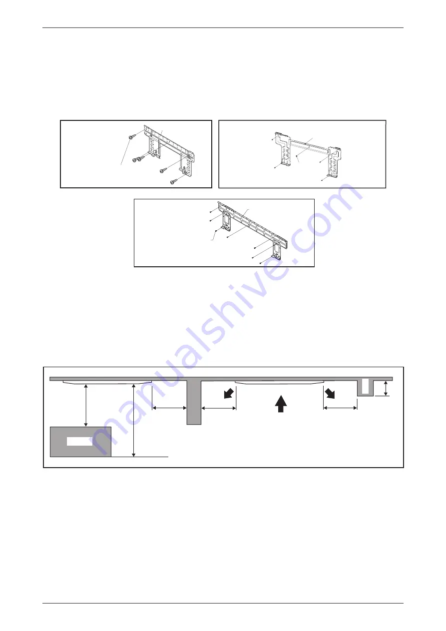
Mounting Installation Plate
Ensure that the wall is strong enough to withstand the weight of the unit. Otherwise, it is necessary to
reinforce the wall with plates, beams or pillars.
Use the level gauge for horizontal mounting, and fix it with 5 suitable screws for FWW02/03/04L and 7
suitable screws for FWW05/06L.
In case the rear piping draws out, drill a hole 65mm in diameter with a cone drill, slightly lower on the outside
wall (see figure).
Mounting plate
Mounting plate fixing screw
FWW05/06L
Mounting plate
Mounting plate fixing screw
FWW02/03/04L
Mounting plate
Mounting plate
fixing screw
(ALTERNATIVE INSTALLATION PLATE)
FWW02/03/04L
Model: FWKE
1. Preliminary Site Survey
Be sure to read this manual before installing the air-conditioner indoor unit.
• Voltage supply fluctuation must not 10% of rated voltage. Electricity supply lines must be
independent of welding transformers which can cause high supply fluctuation.
• Ensure that the location is convenient for wiring, piping and drainage.
• Do not exert pressure on the resin parts when opening the unit or when moving it after opening.
• Do not move the unit from packaging while moving, until it reaches the installation site. Use safe material
or protection plates when unpacking it or lifting it to avoid damage or scratches to the unit.
e
r
o
m
r
o
m
5
.
0
e
r
o
m
r
o
m
5
.
0
e
r
o
m
r
o
m
5
.
0
3m or more
3m or more
1m or more
Floor
Obstacle
Bea
m
• Ensure a location where:
a) Drainage can be done easily.
b) Convenient for wiring and piping.
c) Which have enough space for installation and service work.
d) Where no risk of flammable gas leakage.
e) When free from any obstacles in path of cool air discharge and warm air return and must allow
spreading of air throughout the room (near the center of the room).
f) Must be provided clearance for indoor unit from the wall and obstacles as shown in figure below.
g) The installation place must be strong enough to support a load 4 times the indoor unit weight to avoid
amplifying noise and vibration.
h) The installation place (hanging ceiling surface) must be assuring levelness and the height in the ceiling
is 350mm or more.
i) The indoor unit must be away from heat and steam sources (avoid installing it near an entrance).
Summary of Contents for FUD Series
Page 2: ......
Page 4: ...Table of Contents ii...
Page 71: ...67 Fan Performance Chart...
Page 76: ...72 Fan Performance Chart...
Page 77: ...73 Fan Performance Chart...
Page 78: ...74 Fan Performance Chart...
Page 79: ...75 Fan Performance Chart...
Page 80: ...76 Fan Performance Chart...
Page 81: ...77 Fan Performance Chart...
Page 82: ...78 Fan Performance Chart...
Page 88: ...84 Fan Performance Chart...
Page 125: ...121 Wiring Diagrams Model FWC08 10 12G MSP Model FWC02 03 04 06 08 12G EC LSP MSP...
Page 126: ...122 Wiring Diagrams Model FUD20B Model FUD25B...
Page 127: ...123 Wiring Diagrams Model FUD30B...
Page 131: ......


