13
Application Information
Unit Installation
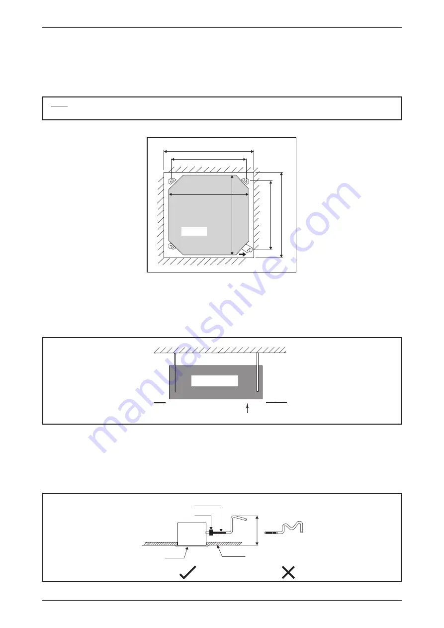
• Measure and mark the position for the hanging rod. Drill the hole for the angle nut on the ceiling and fix the
hanging rod.
• The installation template is extended according to temperature and humidity. Check on dimensions in use.
• The dimensions of the installation template are the same as those of the ceiling opening dimensions.
• Before ceiling laminating work is completed, be sure to fit the installation template to the indoor unit.
NOTE
Be sure to discuss the ceiling drilling work with the installers concerned.
FWKE
Unit size 820mm
Piping Direction
Ceiling Opening Site = 890mm
Ceiling Opening Site = 890mm
Hanging Rod Site = 790mm
Unit size 820mm
Unit
Hanging Rod Site = 621mm
Unit Hanging
• Confirm the pitch of the hanging rod.
• Hold the unit and hang it on the hanging rod with the nut and washer.
• Adjust the unit height to 35.0mm between the indoor unit bottom surface and the ceiling surface.
• Confirm with a level gauge that the unit is installed horizontally and tighten the nut and bolt to prevent unit
failing and vibration.
• Open the ceiling board along the outer edge of the paper installation template.
Indoor Unit
Ceiling
Board
35.0 mm
35.0mm
Indoor Unit
Ceiling
Board
Drain Piping Work
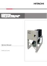
• Drain pipe must be in downward gradient for smooth drainage.
• Avoid installing the drain pipe in up and down slope to prevent reversed water flow.
• During the drain pipe connection, be careful not to exert extra force on the drain connector at indoor unit.
• The outside diameter of the drain connection at the flexible drain hose is 20mm.
• Be sure to execute heat insulation (polyethylene foam with thickness more than 8.0mm) on the drain
piping to avoid the condensed water dripping inside the room.
Pipe Clamp
Ceiling
700.0mm
or less
Panel
Flexible Hose
Indoor
Unit
Summary of Contents for FUD Series
Page 2: ......
Page 4: ...Table of Contents ii...
Page 71: ...67 Fan Performance Chart...
Page 76: ...72 Fan Performance Chart...
Page 77: ...73 Fan Performance Chart...
Page 78: ...74 Fan Performance Chart...
Page 79: ...75 Fan Performance Chart...
Page 80: ...76 Fan Performance Chart...
Page 81: ...77 Fan Performance Chart...
Page 82: ...78 Fan Performance Chart...
Page 88: ...84 Fan Performance Chart...
Page 125: ...121 Wiring Diagrams Model FWC08 10 12G MSP Model FWC02 03 04 06 08 12G EC LSP MSP...
Page 126: ...122 Wiring Diagrams Model FUD20B Model FUD25B...
Page 127: ...123 Wiring Diagrams Model FUD30B...
Page 131: ......


