Installation manual
16
FWF
Fan coil units
4PW64524-1 – 09.2010
4 Install the fan coil unit
4.5.3 Fill the water circuit
Notice
Water quality must be according to EU directive 98/83 EC.
Notice
Use of glycol is allowed, but the amount shall not exceed 40% of the volume. A
higher amount of glycol may cause damage to the hydraulic components.
During filling, it might not be possible to remove all air in the system. Remaining air can be
removed during the first operating hours of the unit. The air can be removed from the unit
through the manual air purge valve. For the location of the air purge valve on the unit, refer
to figure
“Water piping connection” on page 14
.
1
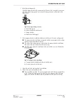
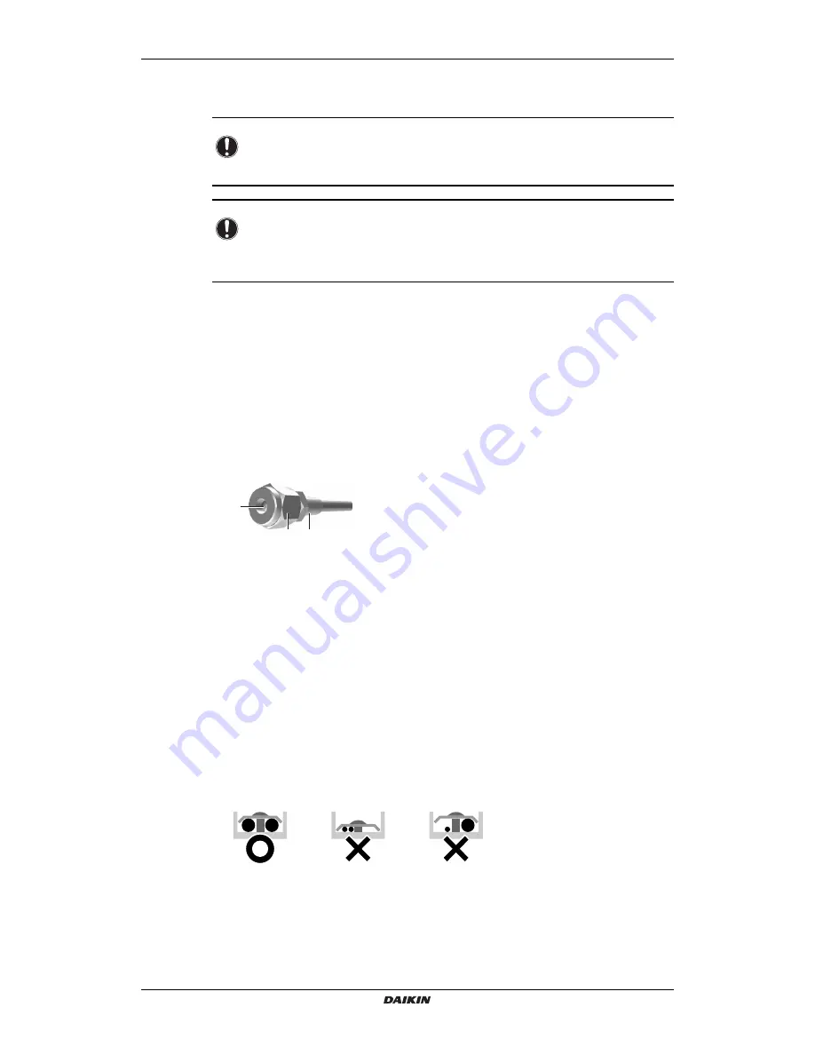
Open the air purge valve (refer to figure
“Air purge valve” on page 16
) by turning the nut
2 times.
2
Push the springy core (refer to figure
“Air purge valve” on page 16
) to let off superfluous
air from the unit water circuit(s).
3
Close the nut.
4
Additional filling with water afterwards might be required (but never through the air
purge valve).
a
b
c
Fig. 4.11: Air purge valve
a
Air purge
b
Nut
c
Springy core
Connect the electrical wiring
4.6
Connect the electrical wiring
Precautions
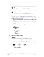
Observe the notes mentioned below when connecting the electrical wiring.
■
Do not connect wires of different gauge to the same power supply terminal. Looseness in
the connection may cause overheating.
■
Do not connect wires of different gauge to the same grounding terminal. Looseness in the
connection may deteriorate the protection.
■
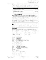
When connecting wires of the same gauge, connect them according to the figure below.
Fig. 4.12: Terminal wiring
Summary of Contents for FWF02B7TV1B
Page 39: ...NOTES...


