FWF
Fan coil units
4PW64524-1 – 09.2010
Installation manual
19
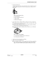
4 Install the fan coil unit
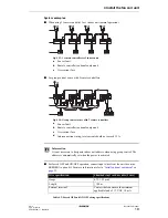
System examples
■
When using 1 remote controller for 1 indoor unit (normal operation)
Fig. 4.13: 1 remote controller for 1 indoor unit
■
For group control or use with 2 remote controllers
Fig. 4.14: Group control or use with 2 remote controllers
■
For forced OFF and ON/OFF operation, connect input wires from the outside on the
EKROROA option kit. For more information refer to
“Install optional equipment” on
page 25
.
Table 4.2: Forced OFF and ON/OFF wiring specifications
Connect the electrical wiring
P
1
1
N
L
a
2
P
2
F
1
F
2
P
1
1
N
L
2
P
2
F
1
F
2
P
1
1
N
L
2
P
2
P
1
P
2
P
1
P
2
P
1
P
2
P
1
P
2
F
1
F
2
P
1
1
N
L
2
P
2
F
1
F
2
c
b
a
Fan coil unit
b
Remote controller (optional equipment)
c
Overcurrent fuse
P
1
1
a
2
P
2
F
1
F
2
P
1
1 2
P
2
F
1
F
2
P
1
1
N
L
2
P
2
P
1
P
2
P
1
P
2
P
1
P
2
F
1
F
2
P
1
1 2
P
2
F
1
F
2
b
d
c
a
Fan coil unit
b
Remote controller (optional equipment)
c
Overcurrent fuse
d
Interconnection wiring: total current should not exceed 12 A.
Information
It is not necessary to designate indoor unit address when using group control. The
address is automatically set when the power is activated.
Wire specification
Sheathed vinyl cord or cable (2 wire)
Gauge
0.75-1.25 mm²
Length
≤
100 m
External terminal
Contact that can ensure the minimum
applicable load of 15 V DC, 10 mA
Summary of Contents for FWF02B7TV1B
Page 39: ...NOTES...


