21
3.1
CONTROL PANEL INSTALLATION AND CONNECTION
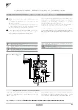
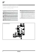
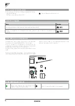
CP L G N
EV
DISPLAY
AIR
H2
CONNETTORE
STEP MOTOR
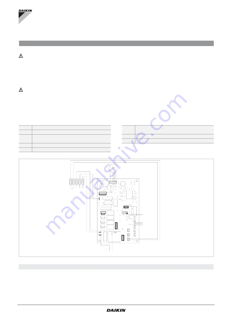
Connection diagram
H2
water temperature probe 10 kΩ
M1
fan motor DC inverter
EV
water solenoid valve (230V/50Hz 1A powered
output)
L-N
230V/50Hz electrical power supply connection
G
protective conductor
CP
presence sensor input (if closed, the fan coil
goes into stand-by.)
AIR
Optional air probe
DISPLAY
control panel (display) wiring
Before you connect the cooler-radiator, make sure
that:
- the voltage and frequency match the values on the
device’s nameplate.
-
The power line has an efficient ground connection and
is appropriately sized for the unit’s maximum current
absorption (minimum cable section: 1.5 mm
2
).
If you need to replace the power cable, contact only
the technical customer service or qualified staff, in
compliance with the applicable national laws.
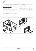
You can use a cable embedded in the wall in the position
traced with the installation template to make the electrical
connection (recommended connection for devices
installed in the upper part of the wall).
In any case, you must check that the power supply is
protected against overload and/or short-circuits.
In order to prevent any risk of electric shock, it is essential
to disconnect the main circuit breaker before making any
electrical connections and performing maintenance on the
equipment.
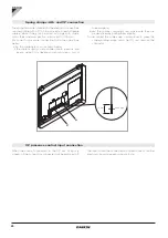
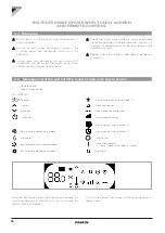
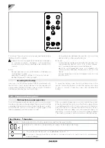
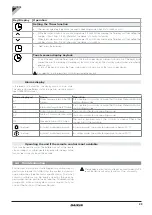
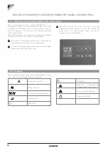
Board connections with TOUCHPAD AND REMOTE CONTROL
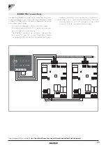
CP presence contact input connection
When the CP contact opens (connected to a clean
contact, not live) the unit is in stand-by mode and the
display reads "CP".
Through this contact, you can connect an external device
that inhibits the unit as: opening window contact, remote
on/off, infrared presence sensor, enabling badge, etc.
See paragraph 4 on page 26
for the instructions for use with the Touchpad and remote control.


