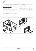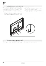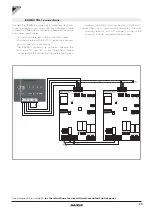
22
BO
CH
INN-FR-B30
N EV1 N EV2
LED
H4
H2
AIR
COMM
M1
MOTOR
L
N
N
L
Y1
H2
GRID
GRID CP
CHILLER BOILER
AIR*
B
A
ON
D
C
ASCII
RTU
- A B +
- A B +
SM
3.2
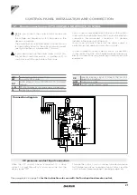
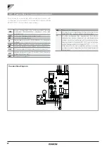
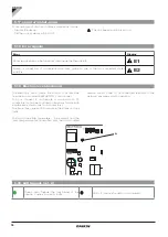
Connection diagram
Connection for remote control panel
The convector is equipped with an electronic board with
continuous fan modulation for connection to wall controller
EKWHCTRL1 (to be ordered separately).
-AB+
serial connection for wall-mounted remote
controller EKWHCTRL1 (respect the AB
polarisation)
H2**
hot water temperature probe 10 kΩ
M1
fan motor connection
Y1
thermoelectric motor (230V/50Hz 1A powered
output)
L-N
230V/50Hz electrical power supply connection
BO
heating request output (free contact max 1A)
CH
cooling request output (free contact max 1A)
CP
presence sensor input (if closed, the convector
goes into stand-by.)
AIR
Optional air probe (*)
SM
Step motor (diffuser)
*
Connect as an alternative to the air probe of the
EKWHCTRL1 wall-mounted control panel
**
If after powering the equipment the board
detects the probe, the start-up will take place
under normal conditions with minimum water
temperature in heating (30 °C) and maximum
water temperature in cooling (20 °C).
The board can also operate without a water
probe, in such cases the fan stop thresholds will
be ignored


