


Installation
EDUS39-900-F10
26
FXMQ-MF
Drain Pipin
g
Work
<<Ri
g
the drain pipe as shown below and take measures a
g
ainst condensate. Improperly ri
gg
ed pipin
g
could
lead to leaks and eventually wet furniture and belon
g
in
g
s.>>
<<Insulate the drain pipes inside the buildin
g
and the drain sockets.>>
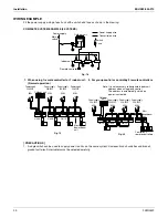
1. Carry out the drain piping.
The drain pipe should be short
w
ith a do
w
n
w
ard slope lo
w
er than 1/100 and should prevent air pockets from forming.
The diameter of the pipe is the same as that of the connecting pipe (PS1B), and should be kept equal to or greater
than that of the connecting pipe.
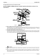
Note:
If converging multiple drain pipes, install according to the procedure sho
w
n belo
w
. (Select an appropriate central
drain pipe thickness for the units they
w
ill be connected to.)
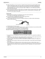
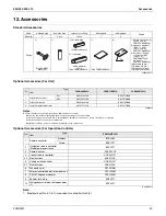
2. After piping
w
ork is finished, check drainage flo
w
smoothly.
Open the
w
ater supply port, add approximately 61in
3
. of
w
ater slo
w
ly into the drain pan and check drainage flo
w
.
(Refer to Fi
g
. 13)
Pools of drainage can cause the drain pipes to clog.
CAUTION
Do not connect the drain pipe directly to se
w
age pipes that smell of ammonia. The ammonia in the se
w
age might
enter the unit through the drain pipes and corrode the heat exchanger.
Electric Wirin
g
Work
GENERAL INSTRUCTIONS
w
All field supplied parts and materials and electric
w
orks must conform to local codes.
Use copper
w
ire only.
For electric
w
iring
w
ork, refer to also “WIRI
N
G DIAGRAM” label attached to the electrical components box lid.
For remote controller
w
iring details, refer to the installation manual attached to the remote controller.
All
w
iring must be performed by an authorized electrician.
This system consists of multiple indoor units. Mark each indoor unit as unit A, unit B..., and be sure the terminal board
w
iring to the outdoor unit is properly matched. If
w
iring and piping bet
w
een the outdoor unit and the indoor unit are
mismatched, the system may cause a malfunction.
A ground fault circuit interrupter capable of shutting do
w
n po
w
er supply to the entire system must be installed.
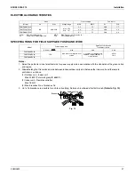
Refer to the installation manual attached to the outdoor unit for the size of po
w
er supply
w
ire connected to the
outdoor unit, the capacity of the ground fault circuit interrupter and s
w
itch, and
w
ire instructions.
Be sure to ground the unit.
Do not connect the ground
w
ire to gas and
w
ater pipes, lightning rods, or telephone ground
w
ires.
Gas pipes : might cause explosions or fire if gas leaks.
Water pipes : no grounding effect if hard vinyl piping is used.
Telephone ground
w
ires or lightning rods : might cause abnormally high electric potential in the ground during
lightning.
Central drain pipe
4in.
or more
(Install
w
ith a do
w
n
w
ard slope of at least 1/100)
Fi
g
. 12
Water supply port
Fi
g
. 13
Summary of Contents for FXMQ-MF
Page 1: ...EDUS 39 900 F10_a AMERICAS FXMQ MF Outdoor Air Processing Unit ...
Page 7: ...Dimensions EDUS39 900 F10 6 FXMQ MF FXMQ72MFVJU FXMQ96MFVJU Unit in 3D065453A ...
Page 8: ...EDUS39 900 F10 Piping Diagrams FXMQ MF 7 4 Piping Diagrams 4D018650C ...
Page 17: ...Fan Performances EDUS39 900 F10 16 FXMQ MF FXMQ96MFVJU 3D065651B ...
Page 19: ...Sound Levels Reference EDUS39 900 F10 18 FXMQ MF FXMQ96MFVJU 4D068577 ...


