


EDUS39-900-F10
Installation
FXMQ-MF
29
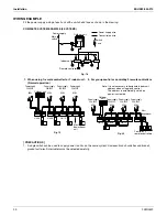
When clamping the
w
ires, be sure no pressure is applied to the
w
ire connections by using the included clamping
material to make appropriate clamps. Also,
w
hen
w
iring, make sure the lid on the electrical components box fits
snugly by arranging the
w
ires neatly and attaching the electrical components box lid firmly. When attaching the
electrical components box lid, make sure no
w
ires get caught in the edges. Pass
w
ire through the
w
iring through
holes to prevent damage to them.
Make sure the remote controller
w
ire, the transmission
w
ire and po
w
er supply
w
ire, ground
w
ire do not pass through
the same locations outside of the unit, separating them by at least 2in., other
w
ise electrical noise (external static)
could cause mistaken operation or breakage.
PRECAUTIONS
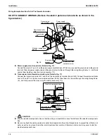
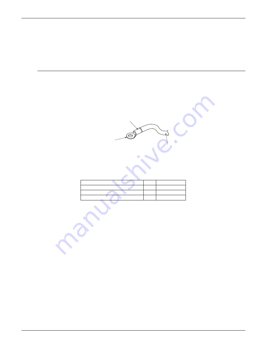
1. Use round crimp-style terminals for connecting
w
ires to the po
w
er supply terminal block.
If unavailable, observe the follo
w
ing points
w
hen
w
iring.
w
Do not connect
w
ires of different gauge to the same po
w
er supply terminal.
(Looseness in the connection may cause overheating.)
Use the specified electric
w
ire. Connect the
w
ire securely to the terminal. Lock the
w
ire do
w
n
w
ithout applying
excessive force to the terminal.
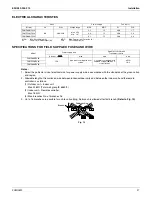
2. Tightening torque for the terminal scre
w
s.
Use the correct scre
w
driver for tightening the terminal scre
w
s. If the blade of scre
w
driver is too small, the head of the
scre
w
might be damaged, and the scre
w
w
ill not be properly tightened.
If the terminal scre
w
s are tightened too hard, scre
w
s might be damaged.
Refer to the table belo
w
for the tightening torque of the terminal scre
w
s.
3. Do not connect
w
ires of different gauge to the same ground terminal. Looseness in the connection may deteriorate
protection.
4. Outside of the unit, keep transmission
w
ire and remote controller
w
ire at least 2in. a
w
ay from po
w
er supply
w
ire and
ground
w
ire. The unit may malfunction if subjected to electrical noise (external static).
5. For remote controller
w
iring, refer to the “I
N
STALLATIO
N
MA
N
UAL OF REMOTE CO
N
TROLLER” attached to the
remote controller.
6.
N
ever connect po
w
er supply
w
ire to the transmission terminal block (X2M). A mistake of the sort could damage the
entire system.
7. Use only specified
w
ire and tightly connect
w
ires to terminals. Be careful
w
ires do not place external stress on
terminals. Keep
w
iring in neat order and so as not to obstruct other equipment such as the electrical components box
lid. Make sure the lid closes tight. Incomplete connections could result in overheating, and in
w
orse case, electric
shock or fire.
Electric
w
ire
Round crimp-style terminal
Attach insulation sleeve
Terminal
Size
Tightening torque
Transmission terminal block (X2M)
M3.5
0.58 – 0.72 ft·lbf
Po
w
er supply terminal block (X1M)
Ground terminal
M4
M5
0.87 – 1.06 ft·lbf
2.23 – 3.01 ft·lbf
Summary of Contents for FXMQ-MF
Page 1: ...EDUS 39 900 F10_a AMERICAS FXMQ MF Outdoor Air Processing Unit ...
Page 7: ...Dimensions EDUS39 900 F10 6 FXMQ MF FXMQ72MFVJU FXMQ96MFVJU Unit in 3D065453A ...
Page 8: ...EDUS39 900 F10 Piping Diagrams FXMQ MF 7 4 Piping Diagrams 4D018650C ...
Page 17: ...Fan Performances EDUS39 900 F10 16 FXMQ MF FXMQ96MFVJU 3D065651B ...
Page 19: ...Sound Levels Reference EDUS39 900 F10 18 FXMQ MF FXMQ96MFVJU 4D068577 ...


