background image

EDUS39-900-F10

Pipin

g

 Dia

g

rams

FXMQ-MF

7

4. Pipin

g

 Dia

g

rams

4D018650C

Summary of Contents for FXMQ-MF

Page 1: ...EDUS 39 900 F10_a AMERICAS FXMQ MF Outdoor Air Processing Unit ...

Page 2: ...nit 1 Features 2 2 Specifications 4 3 Dimensions 5 3 1 Indoor Units 5 4 Piping Diagrams 7 5 Wiring Diagrams 8 6 Capacity Tables 9 7 Operation Limit 12 8 Electric Characteristics 14 9 Fan Performances 15 10 Sound Levels 17 11 Installation 19 12 Accessories 33 ...

Page 3: ... with VRV Outdoor Air Processing Unit Indoor Unit Indoor Unit VRV Series Outdoor Units Air Conditioning Outdoor Air Supply The following restrictions must be observed in order to maintain the indoor units connected to the same system Connection Conditions When outdoor air processing units are connected the total connection capacity must be within 50 to 100 of that of the outdoor units When outdoor...

Page 4: ...f control systems can be deployed including remote control from distances of up to 1640 ft 5 in Group control is not possible between this unit and standard type indoor units Connect remote controllers to each unit Wired remote controller option A central control system compatible with the VRV system can be installed It is not possible to change the discharge air temperature settings from the cent...

Page 5: ... 26 13 Face Area ft 3 01 7 00 7 00 Fan Model D13 4G2DA1 D13 4G2DA1 D13 4G2DA1 Type Sirocco Fan Sirocco Fan Sirocco Fan Motor Output Number of Units W 380 1 380 1 380 1 Air Flow Rate H L cfm 635 988 1 236 External Static Pressure 4 in WG 0 88 0 96 1 03 Drive Direct Drive Direct Drive Direct Drive Temperature Control Microprocessor Thermostat for Cooling and Heating Microprocessor Thermostat for Coo...

Page 6: ...EDUS39 900 F10 Dimensions FXMQ MF 5 3 Dimensions 3 1 Indoor Units FXMQ48MFVJU Unit in 3D065452A ...

Page 7: ...Dimensions EDUS39 900 F10 6 FXMQ MF FXMQ72MFVJU FXMQ96MFVJU Unit in 3D065453A ...

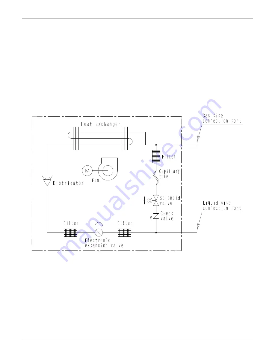
Page 8: ...EDUS39 900 F10 Piping Diagrams FXMQ MF 7 4 Piping Diagrams 4D018650C ...

Page 9: ...Wiring Diagrams EDUS39 900 F10 8 FXMQ MF 5 Wiring Diagrams FXMQ48MFVJU FXMQ72MFVJU FXMQ96MFVJU 3D065426C ...

Page 10: ...ressor operation level 3 A value enclosed in means rated capacity Outdoor air temp FWB FDB 62 66 70 74 78 82 86 90 capacity Btu h Btu h Btu h Btu h Btu h Btu h Btu h Btu h 67 13000 15900 71 13000 15900 18300 75 13000 15900 18300 23300 79 15900 18300 22900 83 18300 22900 37700 87 17900 22600 37300 48300 91 17900 22200 37000 48000 56200 95 21900 36600 47600 55800 59600 Outdoor air temp FWB FDB 19 23...

Page 11: ...peration level 3 A value enclosed in means rated capacity Outdoor air temp FWB FDB 62 66 70 74 78 82 86 90 capacity Btu h Btu h Btu h Btu h Btu h Btu h Btu h Btu h 67 19600 24000 71 19600 24000 27600 75 19600 24000 27600 34700 79 24000 27300 34400 83 27300 34000 56500 87 27000 33700 55900 72600 91 27000 33100 55600 72000 84200 95 32700 54900 71300 83800 89300 Outdoor air temp FWB FDB 19 23 27 31 3...

Page 12: ...ration level 3 A value enclosed in means rated capacity Outdoor air temp FWB FDB 62 66 70 74 78 82 86 90 capacity Btu h Btu h Btu h Btu h Btu h Btu h Btu h Btu h 67 26000 31800 71 26000 31800 36700 75 26000 31800 36700 46200 79 31800 36300 45900 83 36300 45600 75400 87 36000 44900 74700 96600 91 36000 44200 74000 96000 112400 95 43800 73300 95300 111700 119300 Outdoor air temp FWB FDB 19 23 27 31 ...

Page 13: ...ing for too small outdoor air processing capacity 4 The system will not operate in fan mode when the outdoor air temperature is 41 F or below 89 6 C 3D047750 Operation limit cooling Operation limit heating Fan only operation O u t d o o r a i r t e m p F W B Outdoor air temp F DB 23 32 59 66 2 86 92 3 106 7 109 4 2 The discharge air temperature may not match the temperature setting for too large o...

Page 14: ...ot match the temperature setting for too large outdoor air processing capacity Thermostat OFF may be carried out NOTE 1 These figures assume the following operating conditions Indoor and outdoor units Equivalent pipe length 25ft Level difference 0ft 3 The discharge air temperature may not match the temperature setting for too small outdoor air processing capacity 4 The system will not operate in f...

Page 15: ...Electric Characteristics EDUS39 900 F10 14 FXMQ MF 8 Electric Characteristics MOP MOP Max Overcurrent Protection A See Note 5 MCA MOP MOP 15 ...

Page 16: ...EDUS39 900 F10 Fan Performances FXMQ MF 15 9 Fan Performances FXMQ48MFVJU FXMQ72MFVJU 3D065649B 3D065650B ...

Page 17: ...Fan Performances EDUS39 900 F10 16 FXMQ MF FXMQ96MFVJU 3D065651B ...

Page 18: ...tandard JIS conditions Power source 208 230V 60hz 2 The operating values were obtained in an anechoic chamber conversion values 1 Sound levels will vary depending on a range of factors such as the construction acoustic absorption coefficient of the particular room in which the equipment is installed dBA Model 208 230V 60Hz FXMQ48MFVJU 43 FXMQ72MFVJU 48 FXMQ96MFVJU 48 4D068575 FXMQ48MFVJU FXMQ72MFV...

Page 19: ...Sound Levels Reference EDUS39 900 F10 18 FXMQ MF FXMQ96MFVJU 4D068577 ...

Page 20: ...rong enough to take the unit s weight the unit could fall out of place and cause serious injury Where the false ceiling is not noticeably on an incline Where there is no risk of combustible gas leakage Where sufficient clearance for maintenance and service can be ensured Refer to Fig 1 Where the total piping length involving indoor unit and outdoor unit is below the allowable piping length See the...

Page 21: ...lation Check whether the ceiling is strong enough to support the weight of the unit or not If there is a risk reinforce the ceiling before installing the unit Outdoor air processing unit Upper face 26 or more 21 or more Service space 44 or more Service space length in Fig 1 ...

Page 22: ...le Pre set ceilings Once the installation hole is opened in the ceiling where the unit is to be installed pass refrigerant and drain pipe and the power supply transmission and remote controller wire to the unit s pipe and wire connection ports After opening the ceiling hole it might be necessary to reinforce the ceiling frame to prevent shaking or to maintain the levelness of the ceiling Consult a...

Page 23: ...vel or a vinyl tube filled with water to make sure that the unit is level and that the tilt downward slope to the drain socket and air inlet side is within 1 Refer to Fig 5 4 Tighten both upper and lower nuts 1 3 Refer to Fig 4 5 Insulate the four hanger brackets with the sealing pad accessory 6 Insulate the hanger brackets so that the surface and edges of the hanger brackets cannot be seen Refer ...

Page 24: ...ith tape Do not allow anything other than the designated refrigerant to get mixed into the refrigerant circuit such as ir etc If any refrigerant gas leaks while working on the unit ventilate the room thoroughly right away TThe outdoor unit is charged with refrigerant Be sure to use both a spanner and torque wrench together as shown in the drawing when connecting or disconnecting pipes to from the ...

Page 25: ...on for fitting accessory 3 Tighten both edges with clamping material 2 Use the attached pipe accessory 1 for connecting the gas pipes and make sure to insulate the gas pipes using field supplied insulation all the way to the base where they connect to the unit 3 The turning torque of the hexagon head bolts accessory 8 to connect the attached pipe accessory 1 to the unit is 15 9 21 3ft lbf Table 3 ...

Page 26: ...e flux contains fluorine it will damage the refrigerant oil Before brazing local refrigerant piping nitrogen gas shall be blown through the piping to expel air from the piping If your brazing is done without nitrogen gas blowing a large amount of oxide film develops inside the piping and could cause system malfunction When brazing the refrigerant piping only begin brazing after having carried out ...

Page 27: ...pplied parts and materials and electric works must conform to local codes Use copper wire only For electric wiring work refer to also WIRING DIAGRAM label attached to the electrical components box lid For remote controller wiring details refer to the installation manual attached to the remote controller All wiring must be performed by an authorized electrician This system consists of multiple indo...

Page 28: ...es No of branches 16 3 Up to 16 branches are possible for unit to unit cabling No branch is allowed after first branch Refer to Fig 15 Units Power supply Fan motor Model Hz Volts Voltage range MCA MOP W FLA FXMQ48MFVJU 60 208 230 Max 253 Min 187 2 1 15 380 1 7 FXMQ72MFVJU 3 6 15 380 2 9 FXMQ96MFVJU 4 1 15 380 3 3 MCA Min Circuit Amps A MOP Max Overcurrent Protection A W Fan Motor Rated Output W FL...

Page 29: ...e unit through the wiring through hole 2 and firmly secure the wires using the clamp accessory 11 CAUTION Wire the electrical components box so that the wiring is at least 3 8in above the bottom of the electrical components box Be sure to attach the sealing material or putty field supplied to the wiring through holes to prevent the infiltration of water as well as any insects and other small creat...

Page 30: ...ver for tightening the terminal screws If the blade of screwdriver is too small the head of the screw might be damaged and the screw will not be properly tightened If the terminal screws are tightened too hard screws might be damaged Refer to the table below for the tightening torque of the terminal screws 3 Do not connect wires of different gauge to the same ground terminal Looseness in the conne...

Page 31: ... F2 F1 F2 Control box L1 L2 L1L2 P1 P2 P1 P2 F1 F2 T1 T2 P1 P2 P1 P2 F1 F2 T1 T2 L1L2 P1 P2 P1 P2 F1 F2 T1 T2 L1L2 L1L2 P1 P2 P1 P2 F1 F2 T1 T2 L1 L2 Outdoor unit Unit A Unit B Unit C Most downstream unit Power supply 208 230V 60Hz Power supply 208 230V 60Hz Power supply 208 230V 60Hz Power supply 208 230V 60Hz Fig 19 L1 L2 L1 L2 L1 L2 Unit A IN D OUT D F1 F2 F1 F2 Control box P1 P2 P1 P2 F1 F2 T1...

Page 32: ...r tWemperature is 41ºF or lower The unit will stop running to protect itself against cold damage In such case set the AUTOMATIC OPERATION or HEATING OPERATION mode COOLING F OUTDOOR TEMPERATURE TEMPERATURE HUMIDITY DB 66 to 109 Note 30 to 90 Long time operation in a humidity over 90 may cause condensation on the unit and dripping WB 89 or below Air outlet Remote controller Air filter Optional acce...

Page 33: ...ng units should be 50 100 of Outdoor unit capacity In case of using only outdoor air processing units it is same 2 The capacity of outdoor air processing units should be less than 30 of the outdoor unit capacity 2 Restrictions of the control system 1 In case of wiring is mixed with standard indoor units group control by remote controller is not available because the setting temperature are differe...

Page 34: ...1 1 4 Only FXMQ48MFVJU 5 Only FXMQ48MFVJU 6 7 Spring washer M10 2 pcs only for FXMQ72 96MFVJU 8 Hexagon head bolt M10 1 9 16 2 pcs only for FXMQ72 96MFVJU 9 Screws for flange connection M5 16 pcs for FXMQ48MFVJU 28 pcs for FXMQ72 96MFVJU 10 Washers 8 pcs 11 Clamps 10 pcs 12 Installation manual 13 Operation manual No Type FXMQ48MFVJU FXMQ72MFVJU FXMQ96MFVJU Item 1 High efficiency filter 65 KAFJ372L...

Reviews: