11
3.5
Power Supply
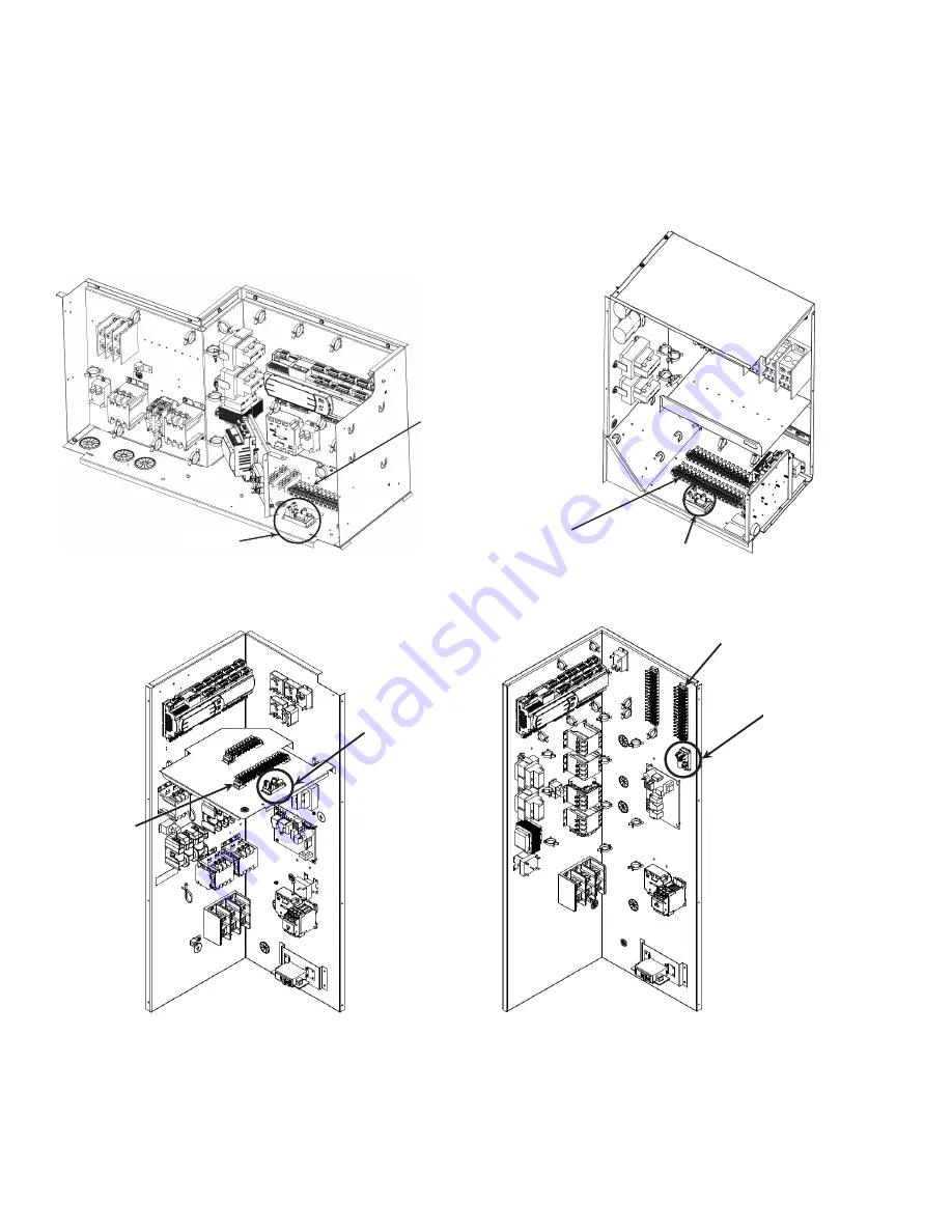
The Power Supply is installed in the RTU’s control box. Figures 5-8 show the suggested installation locations for various
chassis sizes in the Daikin Light Commercial Packaged RTU product line. The actual control box in the field may vary in
appearance but similar installation locations and mounting orientations should be followed. When possible, install the
power supply on a horizontal surface near the low voltage terminal blocks. Make sure that there is a minimum of 0.25”
of space between the power supply and other components. Peel the backing off the adhesive mounting tape and attach
the power supply to the control box.
POWER SUPPLY
24 VAC
SOURCE
POWER SUPPLY
24 VAC
SOURCE
Figure 5 - Small Chassis
Figure 6 - Medium Chassis
POWER SUPPLY
POWER SUPPLY
24 VAC
SOURCE
24 VAC
SOURCE
Figure 7 - Large Chassis
Figure 8 - DB 15-20 Ton Large Chassis
3.6
Wiring Terminations
Refer to the Electrical Wiring Specifications section for point to point connections for the room terminal, power supply,
and the DDC controller. Use care when stripping and terminating wires to eliminate excess exposed copper at each
termination. The ethernet cable connection is only required if the Wi-Fi hot spot feature is utilized.


