IM 1093-1 • SINGLE DUCT VAV TERMINALS 4
www.DaikinApplied.com
I
nsTallaTIon
I
nsTallaTIon
Receiving Inspection
Prior to removing the shipping material, visually inspect the
packing materials. There should be a black plastic strip wrapped
in the clear plastic shrink wrap. If this black plastic strip is
missing, the shipment may have been repacked by the shipper
and you should make note of this on the shipping documents
and inform the delivering carrier. After unpacking the terminal,
check it for shipping damage. If any shipping damage is found,
report it immediately to the delivering carrier. Store units in a
clean, dry location prior to installation. Units with controls are
not recommended for use in ambient temperatures greater
than 95°F. For protection of controls, do not store in ambient
temperatures greater than 135°F. Caution: Do not use the
flow sensor, connecting tubing, or damper shaft as a lift point.
Damage to the flow sensor or controls may result.
Hanging/Installation Requirements
IMPORTANT
If equipped with pneumatic controls, the orientation of the
terminal is critical. The pneumatic controls must be mounted
right side up. The single duct unit must be level or –
10 degrees of horizontal, both parallel to the air flow and at
the right angle of air flow. The control side of the terminal is
labeled with an arrow indicating UP. Unless otherwise noted,
most analog and digital controls may be installed in any
orientation. Check with the local Daikin representative for
verification.
CAUTION
Cautions indicate potentially hazardous situations, which
can result in personal injury or equipment damage if not
avoided .
The equipment is heavy and counted in the ceiling. Use
caution and follow OSHA and SMACNA installation guidelines.
Unless local building codes require hangers, the smaller
size basic single duct terminals may be light enough to be
supported by the ductwork itself. However, when accessory
modules, such as DDC controls, hot water coils, or sound
attenuators are included, the single duct terminal should be
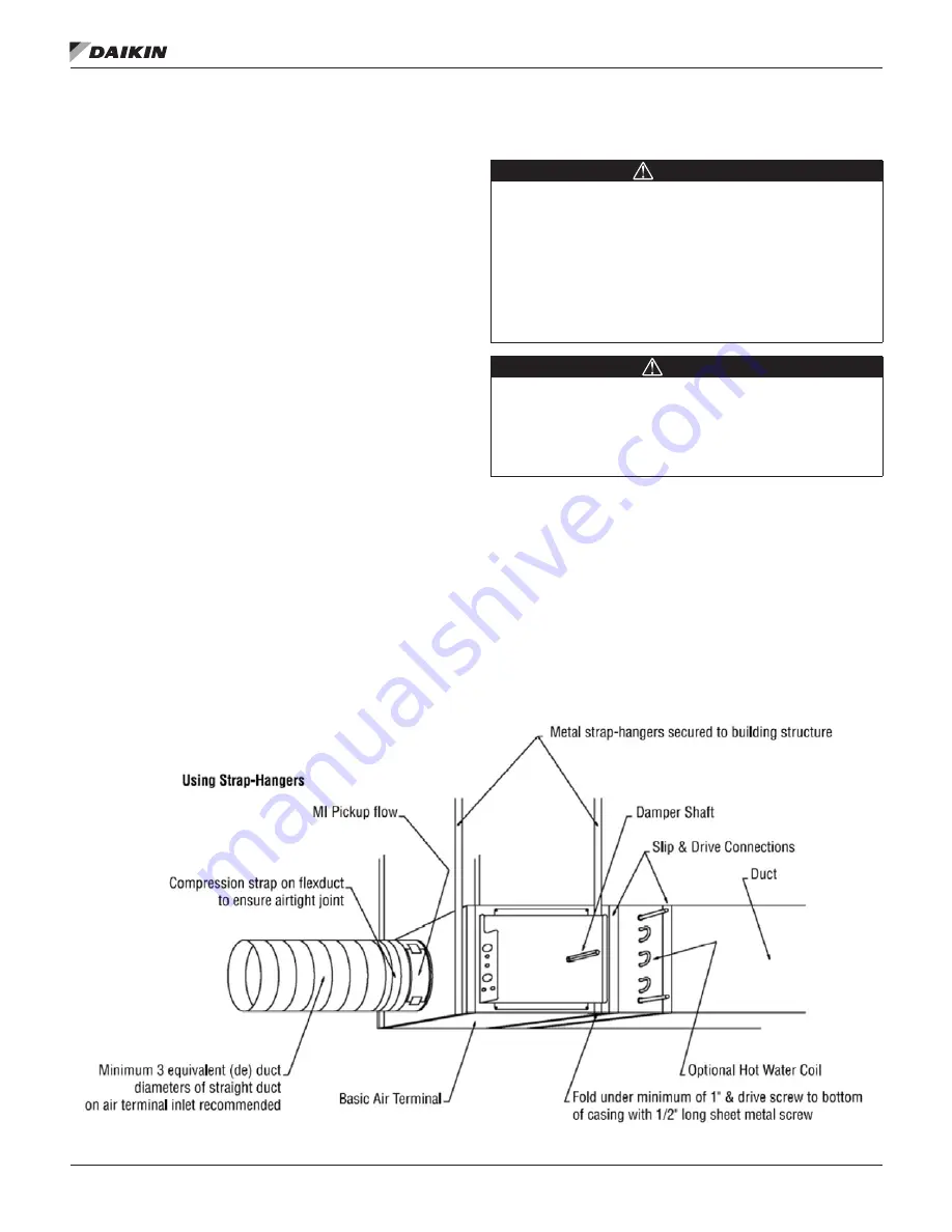
supported directly. Straps screwed directly into the side of the
terminal, trapeze hangers, or the method prescribed for the
rectangular duct on the job specifications may be used (See
Figure 1
and
Figure 2
). The MQTHI5 Single Duct Terminal is
not suitable for outdoor use.
Figure 1: Strap-Hangers


