I
nsTallaTIon
www.DaikinApplied.com
5
IM 1093-1 • SINGLE DUCT VAV TERMINALS
Figure 2: Trapeze-Hangers
Minimum Clearance for Access
Single Duct Air Terminals require sufficient to allow servicing
of the actuator, controls and single electric power hook-
up (if applicable). Horizontal clearance requirements are
dependent upon access panel dimensions which are
indicated on the appropriate submittals (for control panel
enclosure access a minimum of 18" is recommended. See the
appropriate submittal for control panel location). NOTE: These
clearance recommendations are not meant to preclude NEC
requirements or local building codes.
Connecting Ductwork
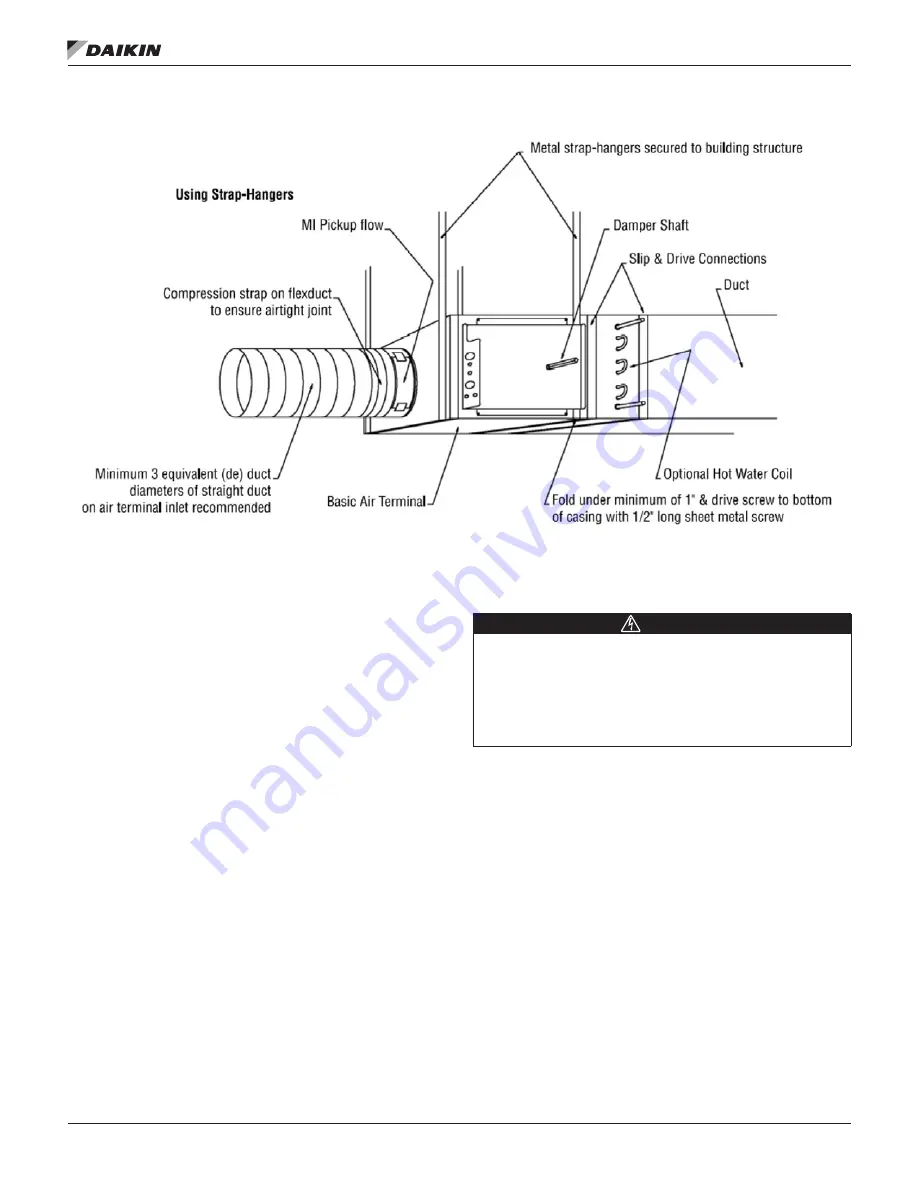
Slip each inlet duct over the inlet collar of the terminal. Fasten
and seal the connection by the method prescribed by the job
specification. The diameter of the inlet duct “D” in inches must
be equal to the listed size of the terminal; e.g. a duct that
actually measures 8 inches must be fitted to a size 8 terminal.
The inlet collar of the terminal is made 1/8 inch smaller than
listed size in order to fit inside the duct.
NOTE:
Do not insert duct work inside the inlet collar of the
assembly.
Inlet duct should be installed in accordance with SMACNA
guidelines. If a single point electronic velocity sensor is
installed, it is recommended that the installer provide three to
five diameters of straight duct at the terminal inlet. The outlet
end of the terminal is designed for use with slip and drive duct
connections (flanged outlets optional). A rectangular duct the
size of the terminal outlet should be attached.
Field Electrical Wiring
DANGER
Electric shock hazard . Can cause personal injury or
equipment damage .
This equipment must be properly grounded. Connections and
service to the MicroTech III Chiller Unit Controller must be
performed only by personnel knowledgeable in the operation
of the equipment being controlled.
•
All field wiring must comply with the local codes and with
the National Electrical Code (ANSI/NFPA 70-2002).
•
When applicable, electrical, control and piping diagrams
are shown on labels attached to the exterior of the single
duct unit.
• Use copper conductors only!
•
All terminal units must be properly grounded per NEC
424-14 and 250.
•
Always check product label for voltage and current data
to determine the proper wire size and current protection.
• The control cabinet contains live electrical parts!
Contacting these parts with the power applied may cause
serious injury or death. The control cover must be closed
prior to applying electric power to the unit.
• These recommendations are not meant to preclude
NEC requirements or local building codes that may be
applicable, which are the responsibility of the installing
contractor.


