www.DaikinApplied.com 51
IM 830-6
Static sensitive components. A static discharge while handling
electronic circuit boards can cause damage to the components.
Discharge any static electrical charge by touching the bare metal
inside the main control panel before performing any service work.
Never unplug any cables, circuit board terminal blocks, relay modules,
or power plugs while power is applied to the panel.
CAUTION
!
Typical Connections For
Temperature Sensor Applications
The low voltage field wiring connections have all been centrally
located within the unit ventilator and are easily accessible.
To simplify field connections, multi-pin plugs are factory provided
and pre-wired with short wire whips
(
).
Each of the
wires in these wire whips is capped and should remain capped
if not used. See
for wiring the remote
mounted temperature sensor to the unit control wiring.
All low voltage field wiring connections must be run in shielded
cable with the shield drain wires connected as shown in the
field wiring diagrams. For sensor terminal wiring details see the
installation manual specific to the sensor being used.
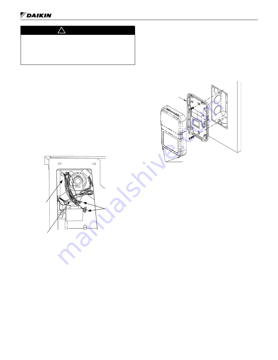
Figure 90: Model AV - Field Wiring Whips with Caps Viewed from
Right End Compartment
Wire Wips for
Field Wiring with
Caps (see the
wiring diagram
provided on the
unit ventilator right
front access panel)
Field Wiring at
back of Local User
Interface (LUI)
Panel
Plug for unit mounted sensor
Sensor Functions
• Display sensor to show room Temperature, fan speed
(AUTO/HIGH/MEDIUM/LOW), system mode (HEAT/COOL
AUTO/OFF), ALARM, Override and occupancy.
Mounting
Location
Avoid mounting on outside walls or in direct sunlight.
Junction Box, (J-Box)
1. Pull the wire through the wall and out of the junction box,
leaving about six inches free.
2. Pull the wire through the hole in the base plate.
3. Secure the back plate to the box using the #6-32 × 1/2
inch mounting screws provided.
4. Screw the plate firmly to the wall so the foam plate backing
is compressed about 50%.
5. Terminate the unit according to the guidelines in the
Termination section.
6. Attach Cover by latching it to the top of the base, rotating it
down and snapping into place.
7. Secure the cover by backing out the lock-down screws
using a 1/16" Allen wrench until it is flush with the bottom
of the cover.
Figure 14: Junction box mounting (hardware is provided
for both junction box and drywall installation.)
Cover lockdown screws 1/16" allen
Mounting
base plate
Drywall Mounting
1. Place the base plate against the wall where you want to
mount the sensor.
2. Mark out the two mounting holes where the unit will be
attached to the wall. Drill a 3/16" hole in the center of each
mounting hole and insert a drywall anchor into the holes.
3. Drill one 1/2" hole in the middle of the marked wiring
through hole area.
4. Pull the wire through the wall and out the 1/2" hole, leaving
about six inches free.
5. Pull the wire through the hole in the base plate.
6. Secure the base to the drywall anchors using the #6 × 1"
mounting screws provided.
7. Screw the plate firmly to the wall so the foam plate backing
is compressed about 50%.
8. Terminate the unit according to the guidelines in the
Termination section.
9. Attach cover by latching it to the top of the base, rotating it
down and snapping it into place.
10. Secure the cover by backing out the lock-down screws
using a 1/16" Allen wrench until it is flush with the sides of
the cover.
Note:
in any wall-mount application, the wall temperature
and the temperature of the air within the wall cavity can
cause erroneous readings.
The mixing of room air and air from within the wall
cavity can lead to condensation, erroneous readings
and sensor failure. To prevent these conditions, Daikin
recommends sealing the conduit leading to the junction
box with fiberglass.


