Part
5. Installation Manual
DCM014A51
Design Guide
129
Off: Hardware error or power Off
F. [LAN LINK]
LED (Green): The LED that indicates the hardware connection is established
normally between the
iTM
and the equipment connected to the LAN port. It is lit when
there is no error.
G. [DIII MONITOR]
LED (Yellow): This LED blinks when data is sent or received via DIII-Net
communication line.
H. [MONITOR]
Key and LED (Orange/Green): By pressing this key, the monitor display turns
On/Off. The color of the LED also changes simultaneously. Off: The monitor is powered off.
On (Orange): The monitor display is off.
On (Green): The monitor display is on.
I. [RESET]
The switch for restarting the
iTM
.
1.4 Side Panel
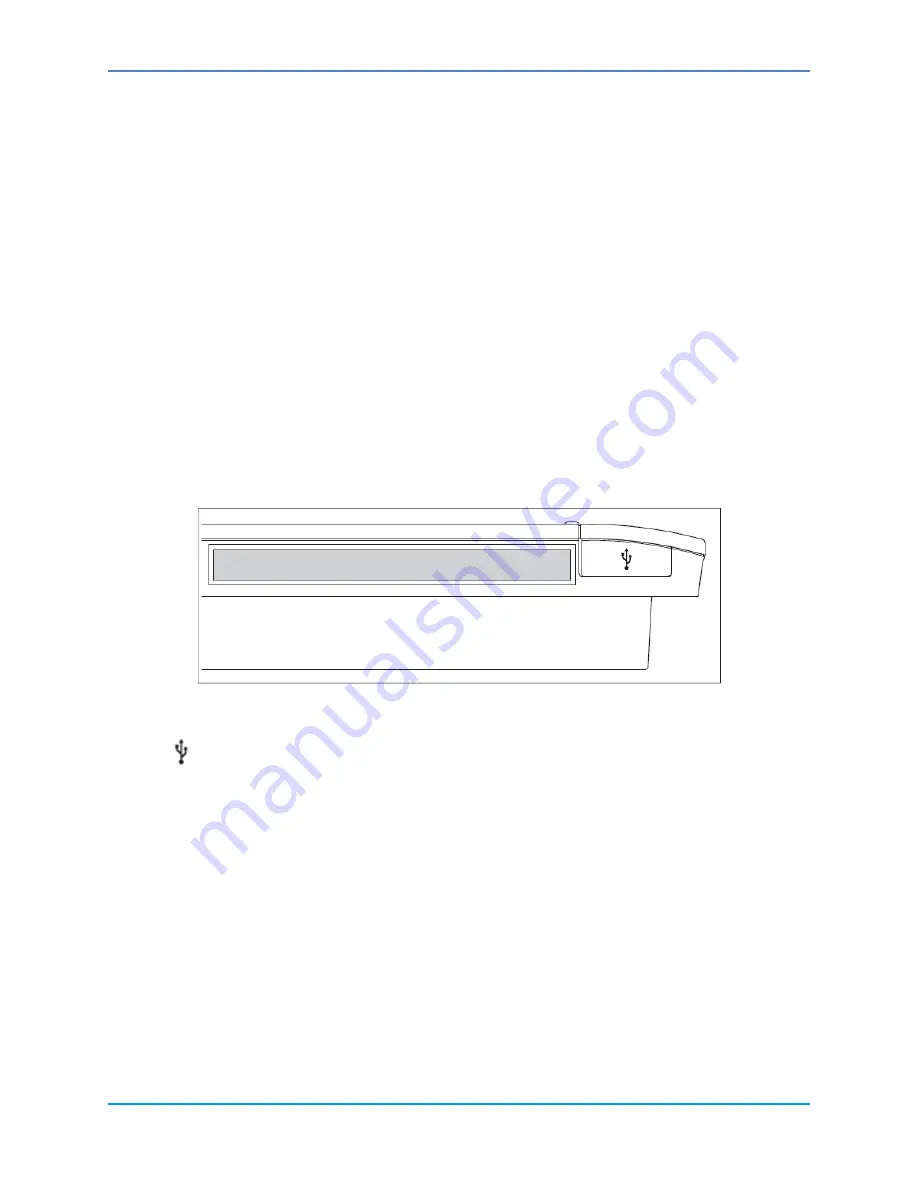
A USB port is located on the left side of the
iTM
. The USB port is used for connecting devices
for making settings, performing maintenance, or other operations after
iTM
installation. The
left side also contains the product label identifying product name, weight, power supply, and
serial number.
Side panel of
iTM
:
Figure 23. Side Panel of intelligent Touch Manager™
[ ]
Open this cover to expose and connect to the USB port. This port can be turned 90 degrees
to the front direction. Connect to this port from the front direction if there is not enough space
on the side.
1.5 Environmental Conditions
Check that the installation environment meets the following conditions:
The ambient temperature is 32 – 104°F.
The ambient humidity is 85% RH or less (without condensation).
The electromagnetic wave does not affect the operation of the iTM.


