15
|
Piping installation
Installer and user reference guide
96
LREN8~12A7 + LRNUN5A7
CO₂ ZEAS outdoor unit and capacity up unit
4P704142-1 – 2022.08
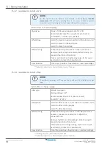
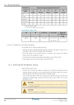
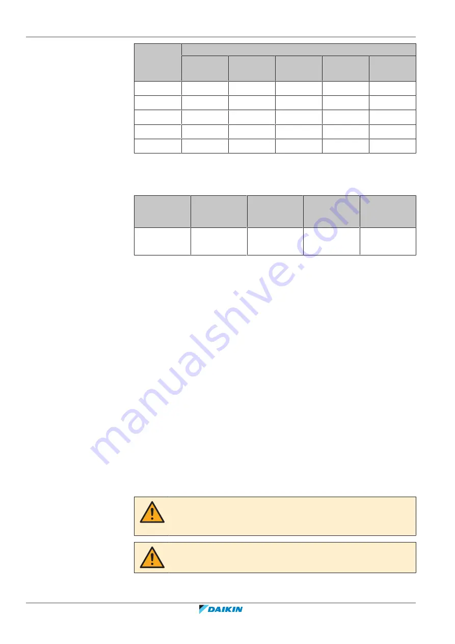
Changeover
valve's kV
value
Maximum piping length (m) for Ø 22.2
(a)
8
elbows
9
elbows
10
elbows
11
elbows
12
elbows
0
(b)
25
24
24
23
22
3-3,49
16
15
15
14
13
3,5-4,49
18
18
17
16
16
4,5-4,99
21
20
19
19
18
5-7,99
22
21
20
19
19
(a)
K65 or equivalent piping
(b)
0 = There is no changeover valve present
Specifications safety valve
PS
Kd
Flow area
Connection
Allowable
temperature
range
90 bar
0.90
15.9 mm
2
1/2" NPT in
1/2" G out
-50/+150°C
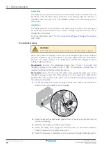
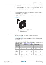
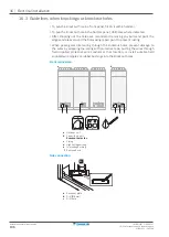
15.3.10 Guidelines to install blow-off piping
The installer has to install the blow-off piping.
▪
Install the outlet of the blow-off piping horizontally (for example, to prevent rain
dripping in). Never point the piping outlet downwards.
▪
Direct the outlet of the blow-off pipe to a location where blown off residue
cannot hurt or harm people or items.
▪
Calculate the maximum piping length according to standard EN 13136.
▪
Thread type must be G1 according to standard ISO 228.
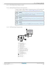
15.4 Checking the refrigerant piping
Keep the following in mind:
▪
The test has to include the safety valve piping. It is therefore necessary that the
pressure passes through the unit. Always keep both liquid and gas stop valves
open during leak test and vacuum drying of the field piping.
▪
Only use R744 dedicated tools (such as gauge manifold and charge hose) that are
designed to withstand high pressures and which will prevent water, dirt or dust
entering the unit.
CAUTION
Do NOT open the stop valve until you have measured the insulation resistance of the
main power supply circuit.
CAUTION
ALWAYS use nitrogen gas for leak tests.

