13
|
About the units and options
Installer and user reference guide
54
LREN8~12A7 + LRNUN5A7
CO₂ ZEAS outdoor unit and capacity up unit
4P704142-1 – 2022.08
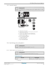
Communication box (BRR9B1V1)
Install the modbus communication box to fully integrate your system with building
control automation networks and other monitoring systems.
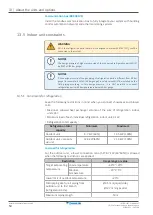
13.5 Indoor unit constraints
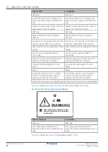
WARNING
ONLY the refrigeration parts that are also designed to work with R744 (CO
2
) shall be
connected to the system.
NOTICE
The design pressure of high pressure side of the connected refrigeration parts MUST
be 9 MPaG (90 bar gauge).
NOTICE
If the design pressure of the gas piping of refrigeration parts is different from 90 bar
gauge (for example: 6 MPaG (60 bar gauge)), a safety valve MUST be installed on the
field piping according to this design pressure. It is NOT possible to connect
refrigeration parts with design pressure below 60 bar gauge.
13.5.1 Constraints for refrigeration
Keep the following restrictions in mind when you connect showcases and blower
coils:
▪
Maximum allowed heat exchanger volume of the sum of refrigeration indoor
units: 35 l.
▪
Minimum load of each individual refrigeration indoor unit: 3 kW.
▪
Refrigeration total capacity:
Refrigeration total
capacity
Minimum
Maximum
Outdoor unit
8.7 kW (60%)
14.5 kW (100%)
Outdoor unit + capacity
up unit
12.6 kW (60%)
21.0 kW (100%)
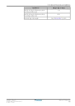
Low load for refrigeration
For the outdoor unit, a lower connection ratio (5.8~8.7 kW (40~60%)) is allowed
when the following restrictions are applied:
Restriction
Usage range or value
Target evaporating
temperature
Low temperature
–40°C~–20°C
Medium
temperature
–20°C~5°C
Lower limit of outdoor temperature
–20°C
Main piping size for all piping from
outdoor unit to first branch
(refrigeration side)
Ø9.5 mm (liquid side)
Ø12.7 mm (gas side)
Maximum piping length
50 m

