Description of Functions and Operation
SiENBE28-901
50
Air Cooled Refrigeration Condensing Unit
(3) Compressor control
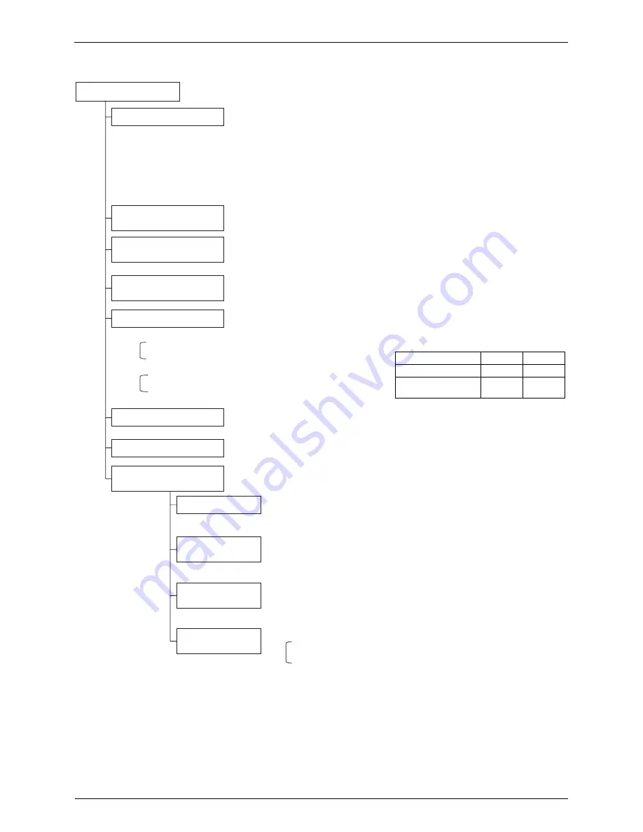
Compressor control
Normal capacity control
High compression ratio
avoidance control
Differential pressure
inversion avoidance control
Oil return control by increasing
the compressor frequency
Control using a reduced LP
Droop control using HP
Droop control using Td
Droop control using
electrical current & INV
Current limit control
Droop control using INV
compressor current
Droop control using INV
compressor fin temperature
STD compressor overcurrent
protection control
• Increase or decrease the compressor frequency using the low pressure as a controlled
variable, in order to achieve the optimum cooling capacity for the target evaporation
temperature (Tst). The target evaporation temperature value used will be the one set by the
dip switches. (For details, see section 2, "Field Settings").
The frequency value will be increased or decreased in steps of 1 every 30 seconds.
• If the low pressure (LP) drops below a pressure equivalent to the target evaporation
temperature (Lpm) –0.015 MPa, the compressor speed will be reduced by one step (every 30
seconds).
• If the low pressure (LP) exceeds a pressure equivalent to the target evaporation temperature
(Lpm) +0.015 MPa, the compressor speed will be increased by one step (every 30 seconds).
However, the thermostat ON/OFF operation will be performed if the load is low.
• If the compression ratio stays above 25 for 10 seconds or more, the compressor speed will be
reduced. (This is intended to protect the compressor scrolls.)
• If the high and low pressure differential is too small, the compressor speed will be increased
according to the actual differential pressure. (This is intended to maintain lubrication.)
• See the "Oil return control" section.
• Reduces the number of compressors being operated or the compressor speed, according to
the actual low pressure and the speed at which the pressure is reduced.
• When stopping the STD compressor:
• Operation mode is not 1, 5 or 7.
• Low pressure (LP) < Rapidly dropping LP
&
• When reducing the INV compressor speed:
• Operation mode = 1
• Low pressure (LP) < LP required for shifting to minimum Hz
&
• Values for rapidly dropping LP and the LP
required for shifting to minimum Hz
LRMEQ**
LRLEQ**
Rapidly dropping LP
0.23MPa
0.02MPa
LP required for shifting
to minimum Hz
0.20MPa
0.02MPa
• The compressor speed is lowered slightly according to the actual high pressure.
High pressure (HP) > 3.23 MPa
• Reduces the compressor speed using the actual discharge thermistor temperature.
The discharge pipe temperature (Td)
≥
115°C for 1 minute or more.
• Control will be performed according to the electrical current setting specified in
Setting Mode 2-2, as the upper limit.
Note that this setting will reduce the cooling capacity.
(For details about setting procedures, see the "Setting Mode 2-2" section)
• Reduces the compressor speed using the inverter actual secondary current.
Inverter secondary current setting for activating droop control: 14.7 A
• Reduces the compressor speed according to the actual inverter fin temperature.
Inverter fin temperature setting for activating droop control: 84°C
• If any of the following conditions is met, the INV. compressor speed will be reduced.
• The STD electrical current value>12.5 A and HP
≥
3.28 MPa for 2 seconds.
• The STD electrical current value>12 A and HP
≥
3.28 MPa for 5 seconds.
or
• If any of the following conditions is met, the STD compressor will be stopped.
• The STD current value>14.95 A for 2.1 seconds.
• The STD current value>13 A for 5 seconds.
• The STD current value>12.35 A for 20 seconds.


