4-24
4.9 Emergency Operation at
Controller Malfunction
●
Manually change
Following manually changing are required for emergency
operation in the case of controller malfunction.
(1) Wiring change of controller
Change wiring to operate compressor, EFM and
CFM.
Refer the details to paragraph 4.9.1.
Preparation parts: Shot circuit connector (fitted
inside of controller)
(2) Fix the opening of EEV, EMV and DMV
Refer the details to paragraph 4.9.2 to 4.9.4.
Preparation parts: Emergency magnet (Parts
No. 1896110)
Note: Fixing of opening for EEV, EMV or DMV is
applicable for emergency use when controller
is normal and EEV, EMV or DMV coil is
malfunction.
●
Operation condition at emergency operation
Temperature can not be controlled. Turn the
circuit breaker ON or OFF to maintain the target
temperature manually.
Operation Mode Operation Condition
Cooling operation
in frozen mode
Compressor: Continuous running
with fixed speed.
EFM : Low Speed
CFM : High Speed
EEV, EMV, DMV: Fixed opening
LSV : Open
Heating operation EFM : High Speed
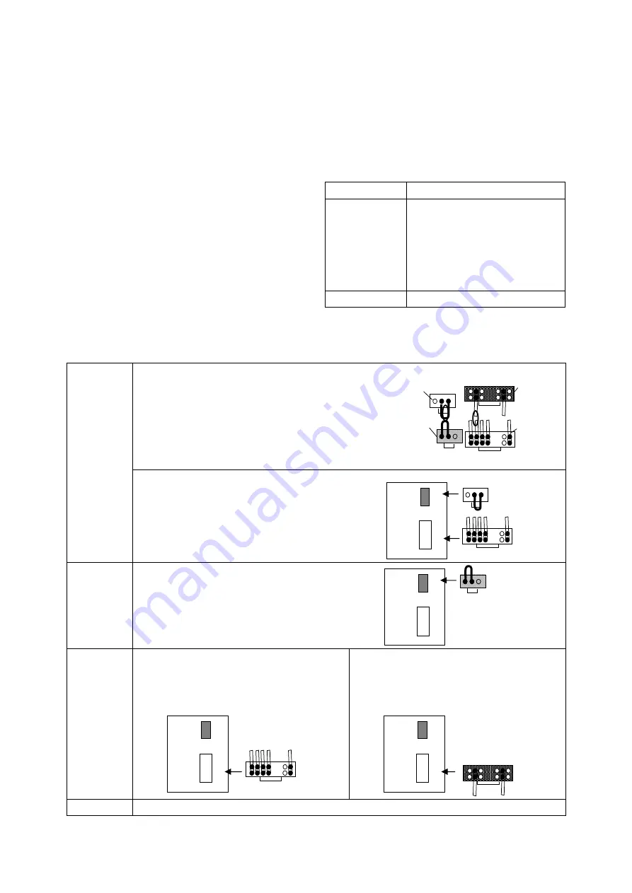
4.9.1 Wiring Change of Controller
Preparation
①
Turn circuit breaker OFF.
②
Disconnect power connector X24A
(
Black
)
located on I/O board. (To de-energized to CPU
board.)
Refer location of X24A to I/O board in
paragraph 1.3.4.
③
Remove short-circuit connectors fitted inside
controller box. (Right figure)
SCC2-2 (Red)
For heating
SCC2-1 (Blue)
For cooling
SCC1-1 (White)
For positive phase
SCC1-2 (Yellow)
For reverse phase
④
Connect SCC1-1
(
White
)
to X31A located
on I/O board and SCC2-1
(
Blue
)
to X32A for
<Cooling>.
Check the insertion direction of the connector.
D
E
R ]
T
A
E
H[
E
UL
B ]
L
O
O
C[
A1
3
X
A2
3
X
PCC1
PCC2
A1
3
X
EMERGENCY
I/O board
SCC1-1(White)
SCC2-1 (Blue)
For cooling
Confirmation
of power
phase
⑤
Turn circuit breaker ON.
If the power supply is in reversed phase,
condenser fan turns reverse.
⑥
In the case of reversed phase, turn circuit
breaker OFF and replace SCC1-1 (White) to
SCC1-2 (Yellow).
A1
3
X
A2
3
X
D
E
R ]
T
A
E
H[
E
UL
B ]
L
O
O
C[
PCC1
PCC2
A1
3
X
EMERGENCY
SCC1-2 (Yellow)
Forcible
operation of
Compressor,
EFM and CFM
<
Cooling Operation
>
Keep
<
cooling operation
>
as it is.
A
1
3
X
A2
3
X
D
E
R ]
T
A
E
H[
E
UL
B ]
L
O
O
C[
PCC1
PCC2
A1
3
X
EMERGENCY
SCC2-1 (Blue)
For cooling
<
Heating Operation
>
1. Turn circuit breaker OFF.
2. Replace SCC2-1 (Blue) to SCC2-2
(
Red
)
for <Heating>.
3. Turn circuit breaker ON.
A
1
3
X
A2
3
X
D
E
R ]
T
A
E
H[
E
UL
B ]
L
O
O
C[
PCC1
PCC2
A1
3
X
EMERGENCY
SCC2-2 (Red)
For heating
Caution
Recheck power supply phase when you operate again after the power is turned OFF.
04̲01-26̲LX10F11B̲En.indd 4-24
04̲01-26̲LX10F11B̲En.indd 4-24
2014/11/19 16:42:30
2014/11/19 16:42:30
https://daikin-p.ru
Summary of Contents for LX10F11B
Page 2: ...Revision A Correction of spelling 2012 9 28 https daikin p ru...
Page 6: ...https daikin p ru...
Page 82: ...https daikin p ru...
Page 92: ...https daikin p ru...
Page 127: ...5 9 5 6 Sequence https daikin p ru...
Page 128: ...5 10 Stereoscopic wiring diagram https daikin p ru...
Page 129: ...Revision A Correction of spelling 2012 9 28 https daikin p ru...

