1-8
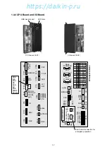
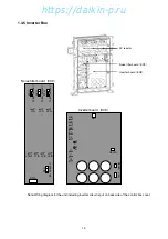
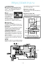
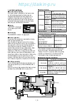
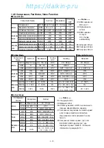
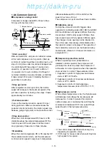
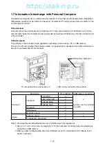
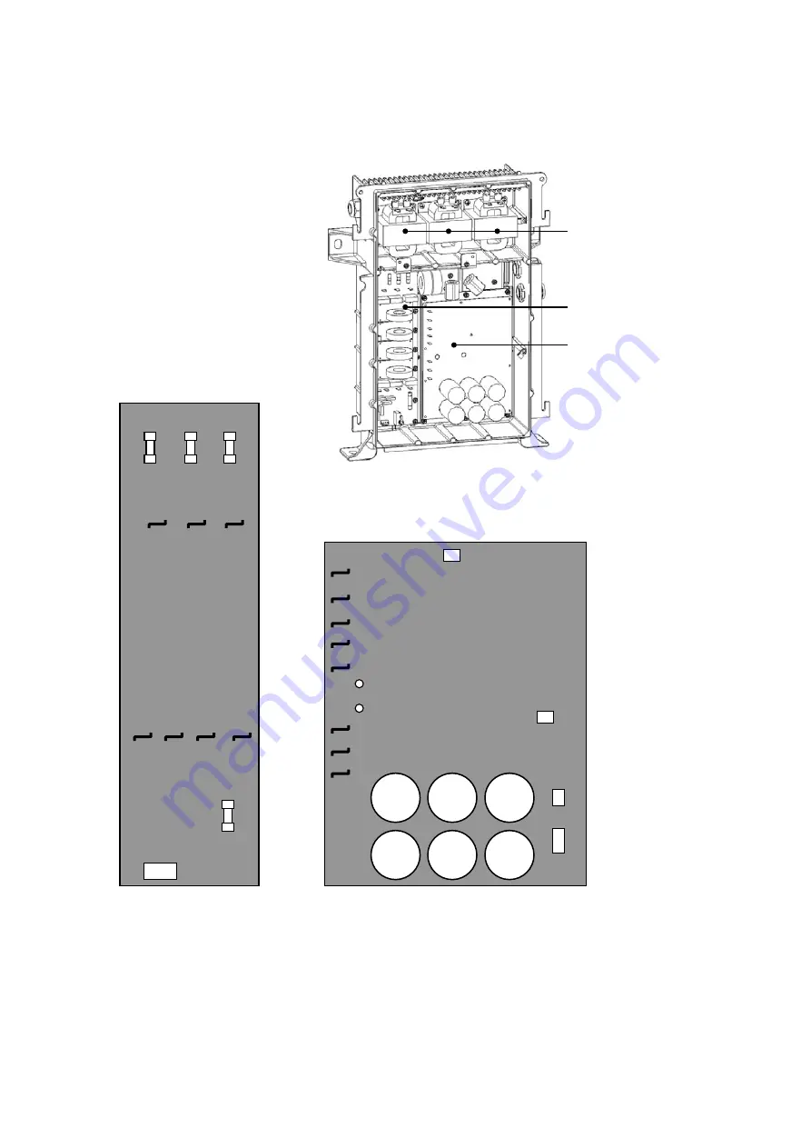
1.3.5 Inverter Box
X6A
X801A
X4A
X802A
U
V
W
L1B
L2B
L3B
L3B
L2B
L1B
L1B-2
L3A
L2A
L1A
12.5A A
C300V
12.5A A
C300V
12.5A A
C300V
8A A
C600V
F5U
F6U
F7U
F8U
X91A
Noise filter board
(
EC9
)
Noise filter board
(
EC9
)
Inverter board
(
EC8
)
AC reactor
Inverter board
(
EC8
)
TP1
TP2
P2
P1
Note: Wiring diagram for the unit including inverter circuit is put on back side of the control box cover.
01̲01-22̲LX10F11B̲En.indd 1-8
01̲01-22̲LX10F11B̲En.indd 1-8
2014/11/19 16:40:23
2014/11/19 16:40:23
https://daikin-p.ru
Summary of Contents for LX10F11B
Page 2: ...Revision A Correction of spelling 2012 9 28 https daikin p ru...
Page 6: ...https daikin p ru...
Page 82: ...https daikin p ru...
Page 92: ...https daikin p ru...
Page 127: ...5 9 5 6 Sequence https daikin p ru...
Page 128: ...5 10 Stereoscopic wiring diagram https daikin p ru...
Page 129: ...Revision A Correction of spelling 2012 9 28 https daikin p ru...

