2
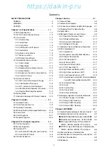
Contents
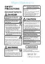
SAFETY PRECAUTIONS
DANGER
………………………………………………
3
WARNING
………………………………………………
3
CAUTION
………………………………………………
3
Chapter 1 Unit Specifications
……………………
1-1
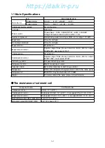
1.1 Main Specifications
……………………………
1-2
1.2 Set Point and Protection Device
………………
1-3
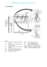
1.3 Construction
……………………………………
1-4
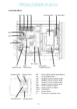
1.3.1 Outside View
………………………………
1-4
1.3.2 Inside View
…………………………………
1-5
1.3.3 Control Box
…………………………………
1-6
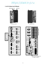
1.3.4 CPU Board and I/O Board
………………
1-7
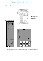
1.3.5 Inverter Box
………………………………
1-8
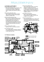
1.3.6 Valves and Functions
……………………
1-9
1.3.7 Sensor Location
……………………………
1-9
1.3.8 Printed Circuit Board
……………………
1-10
1.4 Operation Mode and Control
………………
1-11
1.4.1 Frozen Mode
……………………………
1-11
1.4.2 Chilled Mode
……………………………
1-12
1.4.3 Dehumidification Mode (Option)
………
1-13
1.4.4 Defrost Mode
……………………………
1-14
1.4.5 Compressor, Fan Motor, Valve Function
…
1-15
1.4.6 Common Control
………………………
1-16
1.5 Optional Functions
…………………………
1-17
1.5.1 ASC, Automatic Setpoint Change
……
1-17
1.5.2 Cold Treatment Transport
……………
1-18
1.5.3 ACT, Automatic Cold Treatment
………
1-18
1.5.4 Ventilator Volume Detection (FA Sensor)
…
1-19
1.5.5 Remote Monitoring Receptacle
………
1-19
1.6 Battery Mode
…………………………………
1-19
1.7 Information Interchange with Personal Computer
…
1-20
Chapter 2 Controller
………………………………
2-1
2.1 Operation Panel
…………………………………
2-2
2.2 Controller Functions List
………………………
2-3
2.3 Operation Procedure
…………………………
2-4
2.4 Wake-up Battery (Rechargeable Battery)
…
2-18
2.5 Alarm Code
…………………………………
2-19
2.6 Alarm Diagnosis
……………………………
2-22
2.7 General Diagnosis
……………………………
2-45
Chapter 3 PTI & Periodic Inspection
……………
3-1
3.1 Pre-Trip Inspection
……………………………
3-2
3.2 Manual Inspection
………………………………
3-3
3.3 Automatic PTI
…………………………………
3-5
3.3.1 Automatic PTI Step No. and Contents
…
3-6
3.3.2 Automatic PTI Alarm
………………………
3-6
3.4 Periodic Inspection
……………………………
3-8
Chapter 4 Service
…………………………………
4-1
4.1 Manual Check
…………………………………
4-2
4.2 Automatic Pumpdown
…………………………
4-6
4.3 Connecting and Removing Manifold gauges
…
4-7
4.4 Checking Non-Condensable Gas
……………
4-8
4.5 Sight Glass
………………………………………
4-8
4.6 Refrigerant Recovery and Charge
……………
4-9
4.6.1 Operation Pressure Check
……………
4-10
4.6.2 Refrigerant Recovery
…………………
4-10
4.6.3 Vacuum and Dehydration
………………
4-10
4.6.4 Refrigerant Charge
……………………
4-11
4.7 Electrical Circuit and Servicing Precautions
…
4-12
4.8 Parts Replacement
…………………………
4-13
4.8.1 Compressor
……………………………
4-13
4.8.2 Evaporator Fan and Fan Motor Removing
…
4-15
4.8.3 Inverter Board (EC8)
……………………
4-16
4.8.4 CPU Board (EC1)
………………………
4-16
4.8.5 I/O Board (EC2)
…………………………
4-17
4.8.6 Operation Board (EC3)
…………………
4-17
4.8.7 PT/CT Board (EC7)
……………………
4-17
4.8.8 High Pressure Switch (HPS)
…………
4-18
4.8.9 High Pressure Sensor (HPT)
…………
4-18
4.8.10 Low Pressure Sensor (LPT)
…………
4-19
4.8.11 Electronic Expansion Valve (EEV), Economizer Modulation
Valve (EMV), Discharge Modulation Valve (DMV)
…
4-20
4.8.12 Solenoid Valve
…………………………
4-21
4.8.13 Dryer
……………………………………
4-21
4.8.14 Fusible Plug
……………………………
4-21
4.8.15 Check Valve
……………………………
4-22
4.8.16 Filter and Strainer
……………………
4-22
4.9 Emergency Operation at Controller Malfunction
…
4-23
4.9.1 Wiring Change of Controller
……………
4-23
4.9.2 Fixing of EEV Opening
…………………
4-24
4.9.3 Fixing of EMV Opening
…………………
4-24
4.9.4 Fixing of DMV Opening
…………………
4-25
Chapter 5 APPENDIX
……………………………
5-1
5.1 Standard Tightening Torque for Bolt and Flare Nut
…
5-2
5.2 Temperature Sensor Characteristics
…………
5-3
●
SS/RS/DSS/DRS/EIS/EOS/Eco In/Eco Out/SGS/AMBS
…
5-3
●
DCHS Sensor Characteristics
DCHS1/DCHS2
…
5-4
●
NTC type USDA Sensor Characteristics,
USDA1, USDA2, USDA3, CTS (Option)
……
5-5
●
ST9702-1 type USDA Sensor Characteristics,
USDA1, USDA2, USDA3, CTS (Option)
……
5-6
5.3 Pressure Sensor Characteristics
……………
5-7
5.4 Humidity Sensor Characteristics, HuS (Option)
…
5-7
5.5 R134a Characteristics
…………………………
5-8
5.6 Sequence
………………………………………
5-9
00̲01-04̲LX10F11B̲En.indd 2
00̲01-04̲LX10F11B̲En.indd 2
2014/11/19 16:40:58
2014/11/19 16:40:58
https://daikin-p.ru
Summary of Contents for LX10F11B
Page 2: ...Revision A Correction of spelling 2012 9 28 https daikin p ru...
Page 6: ...https daikin p ru...
Page 82: ...https daikin p ru...
Page 92: ...https daikin p ru...
Page 127: ...5 9 5 6 Sequence https daikin p ru...
Page 128: ...5 10 Stereoscopic wiring diagram https daikin p ru...
Page 129: ...Revision A Correction of spelling 2012 9 28 https daikin p ru...

