background image

2-34

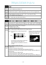
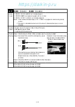
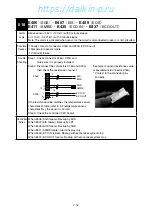
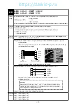
020

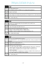
 E417

Alarm 

Logic

Power voltage sensor PT failure

Possible 

Causes

1. Open circuit between connector X61A (PT/CT board)

 X4A (CPU board)

2. Fuse F11U is open (on PT/CT board)
3. Voltage sensor PT failure (on PT/CT board)

Trouble 

Shooting

Step 1.  Check connector X61A (PT/CT board) and X4A (CPU board).

Make sure it is properly installed..

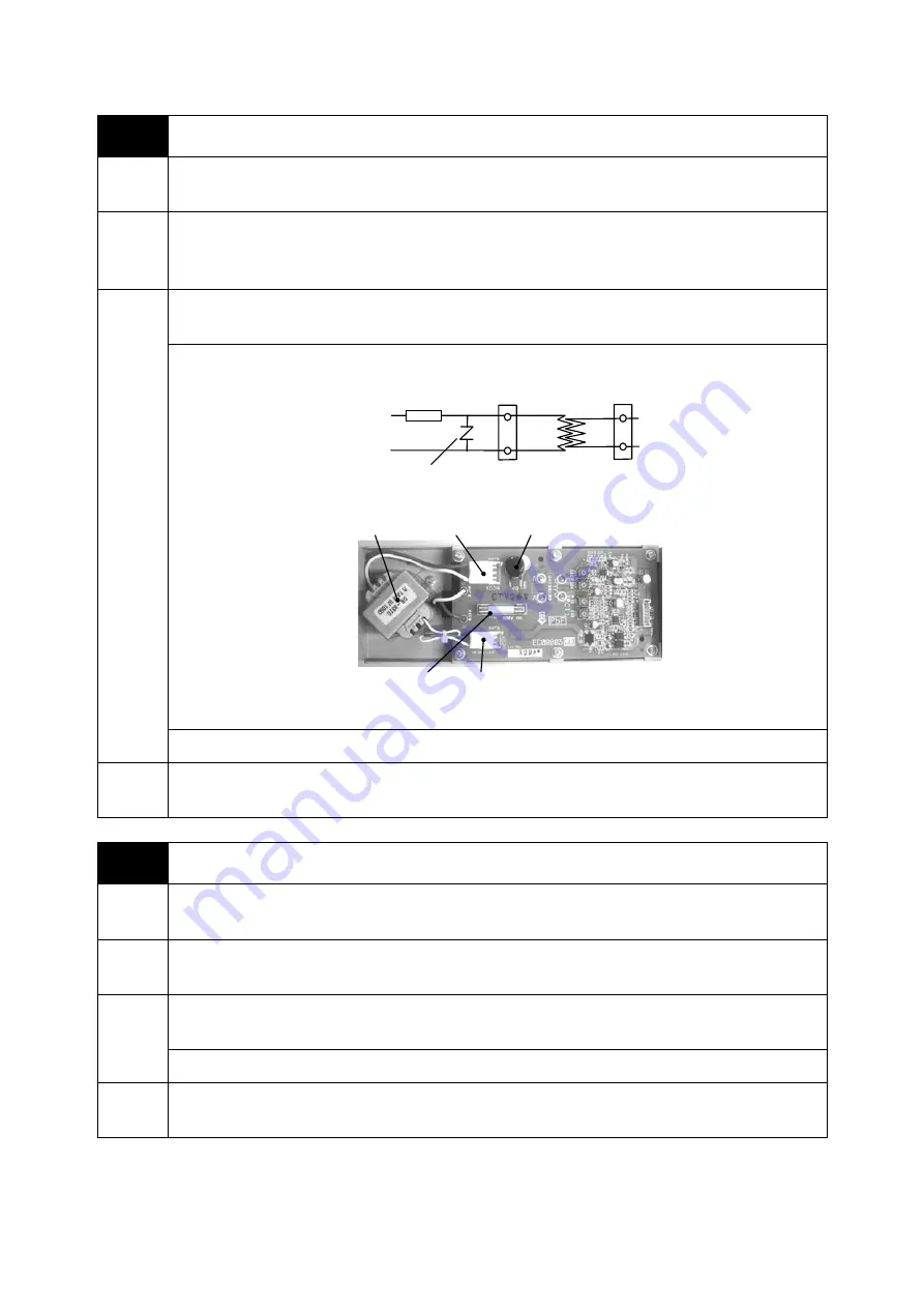
Step 2.  Check if there is short circuit in secondary side of fuse F11U (ZNR, primary side of Tr).

F11U

ZN

Surge absorber

R

X62A

X63A

Tr

PT/CT board

ZNR

X63A

Tr

F11U

X62A

If shorted, replace the PT/CT board.

Step 3. If repeat the alarm with no short circuit, replace the PT/CT board.

Controller 

Action

E417

Alarm display only

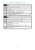
021

 E419

Alarm 

Logic

Current sensor CT failure

Possible 

Causes

Open circuit between connector X61A (PT/CT board)

 X4A (CPU board)

Current sensor CT failure

in PT/CT board

Trouble 

Shooting

Step 1.  Check connector X61A(PT/CT board) / X4A(CPU board) and make sure it is properly 

installed.

Step 2. Replace PT/CT board.

Controller 

Action

E419

Alarm display only

02̲19-44̲LX10F11B̲En.indd   2-34

02̲19-44̲LX10F11B̲En.indd   2-34

2014/11/19   16:38:06

2014/11/19   16:38:06

https://daikin-p.ru

Summary of Contents for LX10F11B

Page 1: ...x 06 6373 7297 Tokyo Office JR Shinagawa East Bldg 11F 18 1 Konan 2 chome Minato ku Tokyo 108 0075 Japan Tel 03 6716 0420 Fax 03 6716 0230 DAIKIN INVERTER CONTAINER REFRIGERATION UNIT Service Manual T...

Page 2: ...Revision A Correction of spelling 2012 9 28 https daikin p ru...

Page 3: ...he container refrigeration unit LX10F B or later including the part names of each operating section how to turn the power on and how to change the temperature setting as well as the functions of the p...

Page 4: ...Pumpdown 4 6 4 3 Connecting and Removing Manifold gauges 4 7 4 4 Checking Non Condensable Gas 4 8 4 5 Sight Glass 4 8 4 6 Refrigerant Recovery and Charge 4 9 4 6 1 Operation Pressure Check 4 10 4 6 2...

Page 5: ...frigerant high pressure control CLASS 1 PRODUCT SPECIFIED BY THE LAW CONCERNING THE RECOVERY AND DESTRUCTION OF FLUOROCARBONS HFC IS USED FOR THIS PRODUCT AS A REFRIGERANT 1 Emission of fluorocarbons...

Page 6: ...https daikin p ru...

Page 7: ...it Board 1 4 Operation Mode and Control 1 4 1 Frozen Mode 1 4 2 Chilled Mode 1 4 3 Dehumidification Mode Option 1 4 4 Defrost Mode 1 4 5 Compressor Fan Motor Valve Function 1 4 6 Common Control 1 5 Op...

Page 8: ...enser fan Propeller fan Condenser fan motor Squirrel cage three phase induction motor Motor output 670W 120W dual speed 4P 6P Defrosting system Hot gas defrosting system Refrigerant control Electronic...

Page 9: ...it Board Fuse Type Protection Circuit Alarm I O board EC2 F1U F10A 250V fast acting type I O board control power DC13 5V 5V 3 3V F2U PCC1 PCC2 CFH CFL EFH EFL HSV RSV LSV ESV F703 F707 E115 E117 F3U S...

Page 10: ...lenoid Valve RSV Reheat Solenoid Valve PRV Pressure Relief Valve Service port Low Pressure Gas line High Pressure Gas line High Pressure Liquid line High Pressure Liquid line 1 3 Construction 1 3 1 Ou...

Page 11: ...EOS Evaporator Outlet Temperature Sensor HuS Humidity Sensor Option RPP2 PC Port Receptacle Option RS Return Air Temperature Sensor SS Supply Air Temperature Sensor USDA1 USDA Sensor 1 Receptacle Opti...

Page 12: ...FL Magnetic Contactor EFM low speed PCC1 Phase Correction Contactor 1 PCC2 Phase Correction Contactor 2 PT CT PT CT Board RCD Modem Option Tr1 Transformer for Operating Circuit LCD board EC4 Sheet key...

Page 13: ...GS AMBS DCHS1 X8A MODEM X12A Operation board X3A Short circuit connectors for emergency operation X30A Tr1 X21A X25A WPS X26A RM X22A HSV RSV SV1 PCC1 PCC2 CFH CFL EFH EFL CBS X28A option X27A X24A CP...

Page 14: ...AC300V 12 5A AC300V 12 5A AC300V 8A AC600V F5U F6U F7U F8U X91A Noise filter board EC9 Noise filter board EC9 Inverter board EC8 AC reactor Inverter board EC8 TP1 TP2 P2 P1 Note Wiring diagram for th...

Page 15: ...ounted at the economizer outlet and inlet EMV is also used for the discharge pipe temperature control and charging control during defrost and heating operation ESV Economizer Solenoid Valve Opening of...

Page 16: ...d energizes magnetic contactors for fan motor EFM CFM and phase correction contactor PCC1 or 2 by receiving order from CPU board At the same time LED lamps wired in parallel with them are energized an...

Page 17: ...eed but it runs low speed when RS drops to 5 0 FULL COOL Modulation When RS drops to SP unit will enter to the modulating cooling Compressor speed is modulated in response to temperature difference be...

Page 18: ...SP 0 5 the unit will return to modulation EFM runs with high or low speed in response to SS Control value varies depending on operating condition HEATING When SS is SP 0 5 unit will be in heating oper...

Page 19: ...ehumidification Operation Dehumidification operation starts when the following conditions are met during modulated cooling in the chilled mode Hu Setting Hu 7 SP 0 7 SS SP 0 7 RS SP 2 0 The above cond...

Page 20: ...rage during defrosting but the IN RANGE LED is kept ON This will avoid misunderstanding that there will be a problem if the IN RANGE LED is turned OFF Defrost Initiation Pull down Short timer 6Hr 12H...

Page 21: ...0 rps 20 130 rps OFF 20 95 rps 20 95 rps EFM H H L 3 H L H OFF H CFM H L OFF 2 H L OFF 2 OFF OFF L H 5 H L OFF 6 Solenoid Valve LSV ON ON OFF OFF ON OFF 4 ON ESV ON ON OFF OFF OFF ON 4 OFF HSV OFF OFF...

Page 22: ...difference between RS or SS and SP at the speed of as low as 20 rps The compressor stops at small heat load condition Calibration valves Turning the unit switch into ON triggers initial operation for...

Page 23: ...settings can be configured as well The temperature inside is raised gradually 0 5 Hr to prevent rapid temperature rise during the pull up operation SP1 SP2 SP3 TM1 TM2 TM3 ASC function starts to oper...

Page 24: ...n paragraph 2 3 Access to setting change 12 Configuration Set in paragraph 2 3 USDA report Temperature record data during cold treatment transport can be prepared in the format in conformity with USDA...

Page 25: ...gradually 0 1 per hour to prevent rapid temperature rise Access to ACT operation Access to 2 6 ACT setting in paragraph 2 3 Indications during ACT operation During USDA operation ACT is displayed in...

Page 26: ...FA sensor at factory referring to 12 Configuration Set in paragraph 2 3 Setting of ventilation volume FA volume Conduct the setting of ventilation volume after the completion of the FA sensor calibrat...

Page 27: ...splay function Return air temperature display RS Supply air temperature display SS High pressure HPT Low pressure LPT USDA 1 USDA 2 USDA 3 temperature CTS temperature Ventilation volume FA Remaining b...

Page 28: ...or USB memory The use of a PC also enables the container number cargo description destination and other information to be sent to and memorized in the controller Description PC connection USB memory c...

Page 29: ...pter 2 Controller 2 1 Operation Panel 2 2 Controller Functions List 2 3 Operation Procedure 2 4 Wake up Battery Rechargeable Battery 2 5 Alarm Code 2 6 Alarm Diagnosis 2 7 General Diagnosis https daik...

Page 30: ...supplied To move to Initialize Menu display after unit ON OFF key ON To move to Menu display while the unit is in operation ENTER To determine the setting contents ESC Returns from the display conten...

Page 31: ...DSS RS DRS FA 4 1 13 18 Trip Start Time and reset 4 1 19 Running hours and reset CM EFH EFL CFH CFL 4 1 20 24 Sensor Information Air SS DSS RS DRS Hus AMBS Cargo USDA1 2 3 CTS Ref EIS EOS DCHS1 2 SGS...

Page 32: ...5 Unit OFF UNIT OFF Initialize Menu Manual Check Config Set Optional Function PTI Menu USB Menu Initialize Menu 10 PTI Menu Refer PTI details to paragraph 3 3 Unit OFF Full PTI Chilled PTI Frozen PTI...

Page 33: ...rmation 5 Service Menu 11 Manual Check Refer manual check details to paragraph 4 1 Preparation Operation Battery Mode Circuit Breaker OFF if optional function set is changed Y M D Y M D Y M D Y M D Y...

Page 34: ...etermine Time setting 3 6 9 12 24 Hr Auto setting AUTO Defrosting will executed automatically in accordance with the state of frost formation occurred on the evaporator coil 2 2 Dehumidification Opera...

Page 35: ...tions 2 3 Humidity Set 1 Press key to select Humidity Setting and press key to determine Humidity Setting 50 95 RH 2 4 USDA Set 1 Press key to select number of sensors and press key to determine 4 sen...

Page 36: ...3 3 Press key to move next setting item Hr and press key then press key to change setting to 48 the first operating Hr and press key to determine Fig 3 3 2 Similarly set the second and the third setti...

Page 37: ...n Fig 4 2 7 G set set It is able to select power consumption limit of the unit in order to continuous operation as much as possible when power supply is not enough capacity 1 Press key to select total...

Page 38: ...1 1 3 13 100pls Discharge gas temp 2 Suction gas temp Economizer Inlet temp Economizer Outlet temp Economizer EV Discharge MV PREV Sensor Information 3 3 PREV 5 1 7 2V Cargo Temp Rec Supply air Temp...

Page 39: ...he day before the circled portion appears at the right end on the screen by pressing key Step 2 Press MENU key to show the Zoom in Zoom out screen Step 3 Zoom in the Date span from 6 Week into 5 Day P...

Page 40: ...ion screen Step 3 To complete the Monitoring Log access to operation screen Service menu Monitoring Log and execute Enter to Stop Caution 1 Remove the USB memory after confirming that the LOGGING USB...

Page 41: ...or F and press to determine 2 Pressure alternate Press key to select kPa PSI or Bar and press to determine 3 Ventilation Volume Alternate Press key to select m3 h or CFM and press to determine Unit Co...

Page 42: ...heat Coil Reheat Coil ON Reheat coil fitted OFF DRS Reheat coil not fitted 12 5 Ventilation FA Ventilation FA LOW FLY With FA sensor Ventilator with insect screen LOW With FA sensor Ventilator without...

Page 43: ...n 13 1 Bulb mode function 13 2 Rail mode function 13 3 AST Automatic change function of set temperature for details refer to paragraph 1 5 1 13 4 ACT Automatic cold treatment function for details refe...

Page 44: ...t inserted Unsupported USB Memory The USB memory has no authentication file Too many files For multiple download of same container ID on the same date overwriting symbol A to Z Download failed Step 1...

Page 45: ...ftware Upload No USB Memory Found Insert or Press ESC to Return Press ESC to Return Press ESC to Return Press ESC to Return Press ESC to Return Step 4 After finishing uploading Pull out a USB memory i...

Page 46: ...tage DC7 6V or more The battery has been charged DC7 5V or less Recharge battery To recharge power the unit for 14 hours or more When power is being supplied recharging will be carried out while the u...

Page 47: ...display F Alarm E807 E304 Blinking Press or key to display alarm code E Alarm OFF F Alarm Diagnosis Alarm code Alarm content Controller action 001 F101 HPS activates within 30 seconds after compressor...

Page 48: ...emperature sensor SGS failure Backup operation 018 E407 Evaporator inlet temperature sensor EIS failure Backup operation 018 E409 Evaporator outlet temperature sensor EOS failure Backup operation 018...

Page 49: ...l frequency much lower than command frequency due to compressor over load Restart after 3 min 105 E526 Actual frequency much higher than command frequency due to external factors Restart after 3 min 1...

Page 50: ...ort circuiting of air passage on air cooled condenser CFM reverse rotation or stopped Repair as needed Stpe 3 DMV check 3 1 Disconnect the connector X11A CPU board then check resistance of DMV coil 3...

Page 51: ...fer to paragraph 1 4 6 for calibration valves 2 3 Fully open the valve body using emergency magnet Refer to paragraph 4 9 2 Then operate the unit without coil 2 1 Resistance between each coil 46 3 2 2...

Page 52: ...2 3 Humidity Setpoint in paragraph 2 3 E305 Defrost Interval setting request Set defrost interval following 2 1 Defrost Interval in paragraph 2 3 E307 Calendar setting request Set 12 11 Controller dat...

Page 53: ...generated when S phase is open E701 Abnormal power voltage is detected during operation AC565V or AC329V One of R S or T phase is open during operation F705 is also generated when S phase is open Pos...

Page 54: ...Causes 1 Abnormal power supply Open phase 2 Broken wire open at power plug or power cable 3 Wire disconnection at unit Trouble Shooting 1 Check if there is open phase on power from power supply equipm...

Page 55: ...and RS is not drop 0 2 for 1 hour Modulation EEV Opening 400 pls continuously for 5 minutes Frozen RS 0 EEV Opening 400 pls and RS is not drop 0 2 for 1 hour RS 0 EEV Opening 400 pls continuously for...

Page 56: ...d time Pump down before defrost EEV close LPT 40kPa or EOS LP T 30 not reached less than 3 times within 300 seconds Auto pump down LSV close Does not drop to LPT 27kP within 210 seconds Possible Cause...

Page 57: ...ambient temperature SP Controller Action E203 Restart after 3 minutes 014 E207 Alarm Logic Defrost can not be completed within 90 minutes The condition EOS 10 was not satisfied five defrosting times c...

Page 58: ...connector X16A and make sure it is properly installed Step 2 Disconnect X16A and check the resistance of sensor Example of sensor resistance value measurement Connector X16A Contact to the connector p...

Page 59: ...board failure Trouble Shooting Step 1 Check connector X16A X20A and make sure it is properly installed Step 2 Disconnect X16 and X20A and check the sensor resistance values X16A DCHS1 X20A DCHS2 17 1...

Page 60: ...en check the resistance of sensor EIS AMBS EOS SGS ECO IN ECO OUT 3 2 6 4 1 5 2 6 4 3 1 5 13 17 14 18 16 15 X16A X20A If the resistance value matches the temperature sensor characteristic table refer...

Page 61: ...ld gauges and compare the value of pressure gauge and LPT value in LCD display Replace LPT if the difference is greater than 10 kPa Step 3 Turn on the circuit breaker and check if there is DC5V input...

Page 62: ...imary side of Tr F11U ZN Surge absorber R X62A X63A Tr PT CT board ZNR X63A Tr F11U X62A If shorted replace the PT CT board Step 3 If repeat the alarm with no short circuit replace the PT CT board Con...

Page 63: ...USDA receptacle is open or short circuited After make jumper between pins A B on USDA CTS receptacle check the continuity on socket X6A CPU board USDA1 USDA2 USDA3 CTS X6A CPU board Sensor receptacle...

Page 64: ...13 11 Black Red Yellow Black Red Black Yellow Input Voltage DC5V Output Voltage Example of voltage check Connector X20A Sensor name Pin No Connector X20A Voltage value Humidity sensor 11 13 DC 5V 12...

Page 65: ...after 3 minutes standby 9 times retry Retry after 4 hours standby 026 E801 Alarm Logic CPU onboard battery failure E307 and E311 are also generated Possible Causes CPU onboard battery is drained due...

Page 66: ...cuit breaker and check if there is DC5V input from the controller FAS X8A No 4 6 Red Black X8A CPU board FAS Black Blue Red Blue Yellow V DC5V 2 4 6 1 3 5 B B R B B Y Input Voltage DC5V Output Voltage...

Page 67: ...e Shooting Step 1 Check if the connector of cable between operation board EC3 and CPU board EC1 is inserted securely Step 2 If there is no connection error between both boards it seems to be operation...

Page 68: ...n DC19A Over current due to compressor overload Inverter board failure Current detection part E525 Compressor speed is down detection of stepping out because actual frequency is low against command fr...

Page 69: ...ailure IPM part IPM Intelligent Power Module F52F E52F is generated 4 times E52F Compressor current sensor failure Inverter board failure Current detection part F53B EEPROM failure when unit is on Inv...

Page 70: ...fter 3 minutes F53C at 4 times retry 104 F53A Alarm Logic Incorrect setting Controller model Possible Causes Does not match controller model setting and compressor model Trouble Shooting Check control...

Page 71: ...Logic Unbalanced power phase is supplied Possible Causes Abnormal power supply Trouble Shooting Regardless alarm is generated restart after 3 minutes standby Operation continues if the external facto...

Page 72: ...re Controller Action E532 Alarm display only 111 Communication Interrupted E5FF Alarm Logic E5FF Communication error between CPU board and inverter board during operation Possible Causes Cable fault o...

Page 73: ...peration Cooling OFF status Display of controller ALARM display See the alarm code when ALARM is generated C Evaporator fan and compressor run but condenser fan does not run Normal operation No action...

Page 74: ...Is the fuse F1U circuit opened Is the voltage at X30A I O board AC20V or less R or T phase is open Faulty power supply voltage drop Disconnection of power cable Power plug failure Replace fuse F1U Ch...

Page 75: ...s the difference in pressure between the ports and 1000 kPa or more Clogging of discharge pipe line Clogged section between the ports and Repair as needed NO Is the difference in pressure between the...

Page 76: ...uction air temperature at condenser 50 C or higher Out of operation range Repair short circuit at discharge air Is the condenser water cooled Visually check for obstructions on condenser coil fin Clog...

Page 77: ...tic contactor for evaporator fan YES Fan rotates reverse Are the current values and coil resistance values for each evaporator fan motor abnormal Replace the evaporator fan motor Install the propeller...

Page 78: ...e low pressure is excessively high Faulty operation of solenoid valve HSV YES YES Is the outlet piping of HSV cold Is the difference in pressure between the pressure gauge and HPT 100 kPa or more Is t...

Page 79: ...of EOS EIS and SGS YES YES YES NO NO NO Operating temperature is fluctuating Faulty discharge pipe temperature sensor DCHS 1 2 Pipe temperature sensor fault EOS EIS SGS Air temperature sensor fault R...

Page 80: ...hten bolts Piping Removed or loosen cramp Auditory check Visual check Fix the cramp Abnormal frosting on compressor Abnormal frosting on compressor and suction pipe Condenser fan stop Defrost complete...

Page 81: ...e monitoring RM has no output Disconnection of TH3 YES YES Is there any short circuit or disconnection on the secondary side of RM receptacle on ship Is there any short circuit or disconnection on the...

Page 82: ...https daikin p ru...

Page 83: ...hapter 3 PTI Periodic Inspection 3 1 Pre Trip Inspection 3 2 Manual Inspection 3 3 Automatic PTI 3 3 1 Automatic PTI Step No and Contents 3 3 2 Automatic PTI Alarm 3 4 Periodic Inspection https daikin...

Page 84: ...ch when high pressure Safety device is raised by stopping the condenser fan motor Control equipment Solenoid valve Inspection of operation open and close and leakage EFM Speed switchover and rotating...

Page 85: ...gh Unit frame Air leakage and clearance Refrigerant system 1 Refrigerant leakage 2 Refrigerant Check for moisture in refrigerant and amount of refrigerant 3 Inspection of service port cap Confirmation...

Page 86: ...essor 3 Condenser fan motor 4 Evaporator fan motor 9 Starting procedure inspection 10 Temperature sensor 1 Installation condition of sensor 2 Alarm indication 11 PT CT voltage and current Alarm indica...

Page 87: ...letion of Short PTI Frozen PTI Short PTI and Frozen PTI are performed It terminates as soon as abnormalities are found after the completion of Short PTI Access 1 Press MENU key at preparation display...

Page 88: ...as normal operation Same as normal operation Same as normal operation Same as normal operation P03 EFM check T031 EFM operation current is large at high and low speed Faulty motor coil Check motor coi...

Page 89: ...ailure HPT failure Gas leakage from manifold gauges Check HPT Compare to manifold gauges Remove manifold gauges T202 Does not reset T203 HPS High pressure does not rise HPS does not operate T204 HPS H...

Page 90: ...e gland 3 Internal cleaning 5 Air leakage from unit casing Air leakage and clearance 6 Seal inspection and replacement Ventilator cover packing 7 Painted area recondition Touch up paint 1 Compressor 2...

Page 91: ...1 Contact point inspection 2 Replace the contact on evaporator fan motor 3 Replace the contact on condenser fan motor 8 Electric insulation check 1 Power cable and plug 2 Compressor 3 Evaporator fan m...

Page 92: ...https daikin p ru...

Page 93: ...aporator Fan Motor Removing 4 8 3 Inverter board EC8 4 8 4 CPU board EC1 4 8 5 I O board EC2 4 8 6 Operation board EC3 4 8 7 PT CT board EC7 4 8 8 High Pressure Switch HPS 4 8 9 High Pressure Sensor H...

Page 94: ...when the Manual Check is completed Manual Check Function ON OFF Check PCC CFH CFL EFH EFL CM HSV RSV LSV ESV RM Circuit HuS Sensor Reading HuS Sensor Calibration SS DSS RS DRS FA option Trip Start Ti...

Page 95: ...ESV ON OFF Check 11 RM Remote Monitoring Circuit Check Option Follow the same procedure for RM Defrost Circuit and RM In Range Circuit checks 11 2 RM Defrost Circuit Check 11 3 RM In Range Circuit Che...

Page 96: ...ure of Ice bath is stabilized at 0 ESC cancel OFFSET VALUE 0 6 0 4 0 7 0 6 SENSOR VALUE 0 4 0 7 0 1 0 1 SS RS DSS DRS All Sensor Calibration Enter Delete former calibration ESC Return Enter Confirm ES...

Page 97: ...ery mode of 15 Data Information in paragraph 2 3 Setting value of ventilation volume Sensor Information PREV 50 m3 h Ventilation Volume 3 3 18 FA Calibration Option Go to FA Calibration in Manual Chec...

Page 98: ...Termination Close HSV when LPT becomes 0 350kPa then close EEV GOOD is displayed and automatic pumpdown will be terminated Use of Automatic Pumpdown 1 Replacement of Dryer Replace Dryer after automat...

Page 99: ...handle Note Do not fully turn the valve handle clockwise Otherwise the push pin may be broken 2 Removal of manifold gauges Turn the valve handle of coupler counterclockwise the push pin is retracted S...

Page 100: ...rresponding saturation temperature of gauge pressure is higher than the temperature of the outdoor air 4 5 Sight Glass Sight glass shows moisture content in the refrigerant and refrigerant flow rate S...

Page 101: ...iquid refrigerant from port after vacuum and dehydration All specified charge amount of refrigerant can not be charged 2 Gaseous charge By operating unit charge gaseous refrigerant from port for the r...

Page 102: ...charge gaseous R134a and raise system pressure to roughly 20kPa by monitoring with the compound gauge Hold this state for 15 minutes as it is 2 Connect recovery machine and recover the refrigerant 3 O...

Page 103: ...weight of R134a cylinder 2 Charge liquid refrigerant from port All specified charge amount of refrigeration can not be charged 3 By operating unit charge gaseous refrigerant from port for the rest of...

Page 104: ...f the power for facility side Even after turning off the circuit breaker supply voltage is still applied 2 Before inspecting the secondary side of circuit breaker be sure to turn off the circuit break...

Page 105: ...2 pcs pipe receptacles 2 Remove the blind caps from the discharge suction and injection pipe receptacles Compressor removal 1 Remove the compressor cover Fig 2 2 Disconnect the compressor cable from t...

Page 106: ...ening torque for lock nut and flare nut is based on following Discharge pipe 122N m 1200kgf m Suction pipe 122N m 1200kgf m Injection pipe 54 9N m 538kgf m 2 4 Apply silicon to cover each lock nut aft...

Page 107: ...wer supply connector on fan motor d Pull the fan assembly straight out e Remove fan diffuser and replace fan motor The screw of fan fixing nut M14 is reverse direction 2 Installation f Re stall fan in...

Page 108: ...rd 6 mounting bolts Projection Hooking hole Front cover Inverter board Fig 2 Inverter box Mounting the inverter board The inverter board and the right cover are combined Fig 3 1 Peel off the protectiv...

Page 109: ...atest software from the Daikin s web site or request it at Daikin Service Office 4 Necessity of configuration setting Case 1 When using CPU board from Daikin spare part configuration setting is not re...

Page 110: ...peration board when power is supplied 4 8 7 PT CT Board EC7 PT CT board EC7 This printed circuit board has the two functions as a measuring instrument and protective device and provide as an interface...

Page 111: ...g of HPT 1 Insert heat shrink tube into HPT body 2 Connect HPT to joint with check valve Tighten flare nuts A and B using two wrenches Fig 1 3 Conduct gas leakage test and check to make sure no gas le...

Page 112: ...inside LPT connection tube by loosening the flare nut of LPT and tighten the flare nut again 5 Check for make sure there is no gas leakage Suction pipe Two wrenches Joint with check valve Two wrenche...

Page 113: ...of the pipe Remove the fixing plate and the coil Un solder valve piping Solder in the new valve body Braze the new valve body while cooling it with a wet cloth Maximum body temperature 120 248 F or l...

Page 114: ...filter to remove particles in the refrigerant system Replace the dryer if it does not absorb moisture is blocked or if the system has been opened to the atmosphere When installing the new dryer follo...

Page 115: ...alves to below picture 2 Install the new check valve in the direction which an arrow shows 3 Check if there is no gas leakage after completion of brazing Strainer Filter Check valve Spring type Check...

Page 116: ...nergized to CPU board Refer location of X24A to I O board in paragraph 1 3 4 Remove short circuit connectors fitted inside controller box Right figure SCC2 2 Red For heating SCC2 1 Blue For cooling SC...

Page 117: ...eration or the degree of super heat becomes small ATTENTION Make sure to reconnect connector X9A Brown to the socket on CPU board when the operation returns to normal 4 9 3 Fixing of EMV Opening For t...

Page 118: ...in paragraph 1 3 4 Remove fixing plate and DMV coil Bring the emergency magnet into contact with valve head turn the magnet clockwise to open fully There is a small click sound when the valve is fully...

Page 119: ...co In Eco Out SGS AMBS DCHS Sensor Characteristics DCHS1 DCHS2 NTC type USDA Sensor Characteristics USDA1 USDA2 USDA3 CTS Option ST9702 1 type USDA Sensor Characteristics USDA1 USDA2 USDA3 CTS Option...

Page 120: ...e Solenoid valve chamber cover M8 12 3 121 9 1 Fixing plate of evaporator fan diffuser Condenser fan motor Control box door Access panel M10 25 2 247 18 6 M12 42 7 418 31 5 Compressor base M14 Reverse...

Page 121: ...3 441 24 11 22 10 17 62 3 303 23 9 20 98 18 64 3 171 22 7 19 91 19 66 3 045 21 5 18 91 20 68 2 925 20 4 17 96 21 69 2 810 19 2 17 07 22 71 2 700 18 0 16 23 23 73 2 596 17 1 15 43 24 75 2 496 16 3 14...

Page 122: ...3 25 77 231 442 66 150 42 031 26 78 220 975 67 152 40 496 27 80 211 037 68 154 39 024 28 82 201 598 69 156 37 612 29 84 192 629 70 158 36 258 30 86 184 107 71 159 34 959 31 87 176 005 72 161 33 713 32...

Page 123: ...333 17 63 14 320 12 10 61 805 18 64 13 678 11 12 58 491 19 66 13 069 10 14 55 379 20 68 12 491 9 16 62 442 21 70 11 041 8 18 49 684 22 72 11 419 7 19 47 087 23 73 10 922 6 21 44 641 24 75 10 450 5 23...

Page 124: ...3 6 911 12 10 24 510 18 64 6 641 11 12 23 370 19 66 6 383 10 14 22 290 20 68 6 136 9 16 21 270 21 70 5 901 8 18 20 300 22 72 5 675 7 19 19 380 23 73 6 460 6 21 18 510 24 75 5 253 5 23 17 680 25 77 5 0...

Page 125: ...0 2 64 500 1 01 1600 2 13 0 0 50 800 2 95 600 1 11 1700 2 23 100 0 81 900 3 25 700 1 21 1800 2 34 200 1 11 1000 3 56 800 1 32 1900 2 44 900 1 42 2000 2 54 1000 1 52 2100 2 64 Input voltage 5 0V Black...

Page 126: ...166 6 11 12 2 93 0 94 13 4 49 120 2 1182 12 04 171 3 10 14 100 1 02 14 5 50 122 1214 12 38 176 0 9 15 8 108 1 10 15 6 51 123 8 1248 12 72 180 9 8 17 6 117 1 18 16 9 52 125 6 1281 13 06 185 7 7 19 4 12...

Page 127: ...5 9 5 6 Sequence https daikin p ru...

Page 128: ...5 10 Stereoscopic wiring diagram https daikin p ru...

Page 129: ...Revision A Correction of spelling 2012 9 28 https daikin p ru...

Page 130: ...x 06 6373 7297 Tokyo Office JR Shinagawa East Bldg 11F 18 1 Konan 2 chome Minato ku Tokyo 108 0075 Japan Tel 03 6716 0420 Fax 03 6716 0230 DAIKIN INVERTER CONTAINER REFRIGERATION UNIT Service Manual T...

Reviews: