2-44
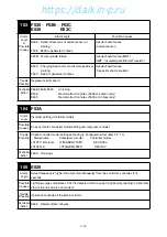
109
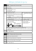
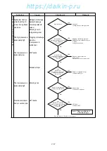
E533
Alarm
Logic
①
Power supply voltage
≧
AC530V or
≦
AC300V.
②
One of phase is open at power supply to inverter.
Possible
Causes
①
Power supply voltage is too high (
≧
AC 530V) or too low (
≦
AC 300V).
②
Check if there is broken wire (open) or open phase at the power supply for inverter
(secondary side of circuit breaker).
Trouble
Shooting
①
Power supply check
Check if the power supply voltage is within
range
(
AC300V
〜
AC530V).
②
Check if there is a broken wire (open)
between L1B, L2B and L3B (INV board) at
the secondary side of the circuit breaker.
①
Provide the power supply voltage within
range.
Electrical parts may have damages.
②
Repaire as needed
Controller
Action
E533
Restart after 3 minutes
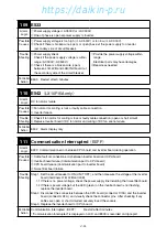
110
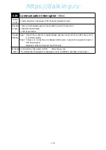
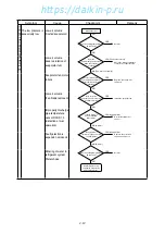
E542
(
LX10F15A only
)
Alarm
Logic
DC fan motor failure
Possible
Causes
①
Fan motor for cooling is lock or faulty cable connection
②
Inverter failure
Trouble
Shooting
①
Check if fan motor for cooling is lock or faulty cable connection (open or short circuit)
②
Replace Inverter board if DC fan motor and wiring of DC fan are no failure.
Controller
Action
E532
Alarm display only
111
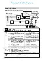
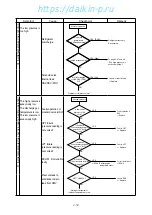
Communication Interrupted
(
E5FF
)
Alarm
Logic
E5FF: Communication error between CPU board and inverter board during operation
Possible
Causes
①
Cable fault or connection error between inverter board and CPU board
②
Inverter board failure (Communication part to CPU board)
③
CPU board failure (Communication part to inverter board)
④
Noise filter board failure
Trouble
Shooting
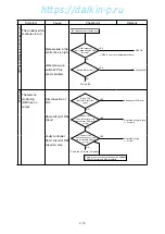
Step 1. Set the circuit breaker to ON (UNIT OFF), and then measure the voltage at the inverter
board (terminals L1B, L2B and L3B).
1.1 If there is no power voltage, check the power supply line including the noise filter board.
1.2 If there is power voltage but the LED (green) on the inverter board is not flashing,
replace the inverter board.
Step 2. Disconnect the connectors between the CPU board (connector X19A) and the inverter
board (connector X4A), and visually check the connector pins. After checking if any
cables are open or short circuited, securely insert the sockets.
Step 3. Replace the inverter board or CPU board.
Controller
Action
Communication Interrupted
(
E5FF
)
Restart after 3 minutes
(
"Communication Interrupted" is displayed on LCD and E903 is recorded on trip report.
02̲19-44̲LX10F11B̲En.indd 2-44
02̲19-44̲LX10F11B̲En.indd 2-44
2014/11/19 16:38:15
2014/11/19 16:38:15
https://daikin-p.ru
Summary of Contents for LX10F11B
Page 2: ...Revision A Correction of spelling 2012 9 28 https daikin p ru...
Page 6: ...https daikin p ru...
Page 82: ...https daikin p ru...
Page 92: ...https daikin p ru...
Page 127: ...5 9 5 6 Sequence https daikin p ru...
Page 128: ...5 10 Stereoscopic wiring diagram https daikin p ru...
Page 129: ...Revision A Correction of spelling 2012 9 28 https daikin p ru...

