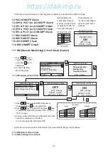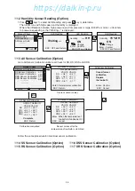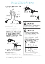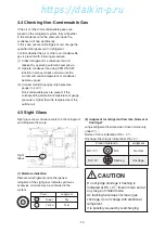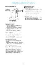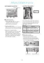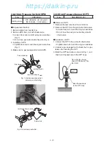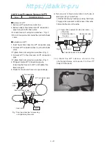
4-12
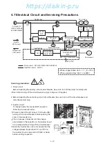
4.7 Electrical Circuit and Servicing Precautions
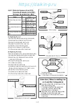
DC400-710V
Inverter box
Control box
C/B
Compressor
AC24V
3 phase AC
380-415V/50Hz
440-460V/60Hz
Inverter board
EC8
ACL
Noise filter
board EC9
Fan motors
SV
Sensors
Modulation Valves
Solenoid Valves
Input to
CPU board
Output from
CPU board
AC
⇒
DC
⇒
Inverter control
Sheet key
EC6
I/O board
EC2
Operation board
EC3
CPU board
EC1
Tr
PT/CT
EC7
LCD
EC4
CFM
EFM
DMV
EEV EMV
CM
Power circuit
380-415V/50Hz 440-460V/60Hz
Operation circuit
AC24V
Servicing precautions
1. Power circuit
Before inspecting the primary side of circuit breaker, be sure to turn off the power for facility side.
※
Even after turning off the circuit breaker, supply voltage is still applied.
2. Before inspecting the secondary side of circuit breaker, be sure to turn off the circuit breaker and
disconnect power plug.
3. Inverter circuit
To inspect inside the inverter BOX, ensure to
follow the instructions below.
①
Ensure to leave the unit at least 10 minutes after
turning off the circuit breaker before opening the
cover of the inverter box.
※
This is because it takes time for the charge
accumulated in the capacitor on the inverter board
to be released after turning off the circuit breaker.
②
Open the inverter box cover and, ensure that the
voltage between the terminal TP1 and TP2 on
the inverter board is lowered to DC50V or below
before starting inspection.
(When stopped) Max. 460
×
1.1
×
2=713V
(When operated) Max. 460
×
1.3=598V
04章̲LX10F11B3̲TR16-02̲En.indd 4-12
04章̲LX10F11B3̲TR16-02̲En.indd 4-12
2016/02/03 16:22:04
2016/02/03 16:22:04
https://daikin-p.ru
Summary of Contents for LX10F11B3
Page 7: ...https daikin p ru ...
Page 83: ...https daikin p ru ...
Page 93: ...https daikin p ru ...
Page 121: ...https daikin p ru ...
Page 129: ...https daikin p ru ...
Page 138: ...6 9 6 6 Sequence AIR WATER COOLED AIR WATER COOLED https daikin p ru ...
Page 139: ...6 10 Stereoscopic wiring diagram AIR WATER COOLED https daikin p ru ...

