4-13
4.8 Parts Replacement
*
After replacing parts, check that the parts are
able to operate correctly.
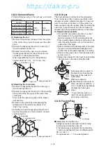
4.8.1 Compressor
●
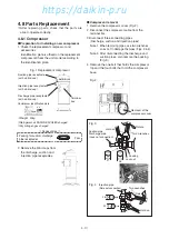
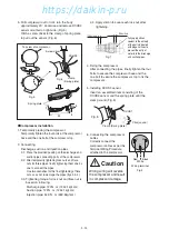
Preparation for installing a new compressor
1. Check the replacement compressor and
accessories.
Identification plate is affixed on the replacement
compressor.Check the unit model according to
the identification plate.
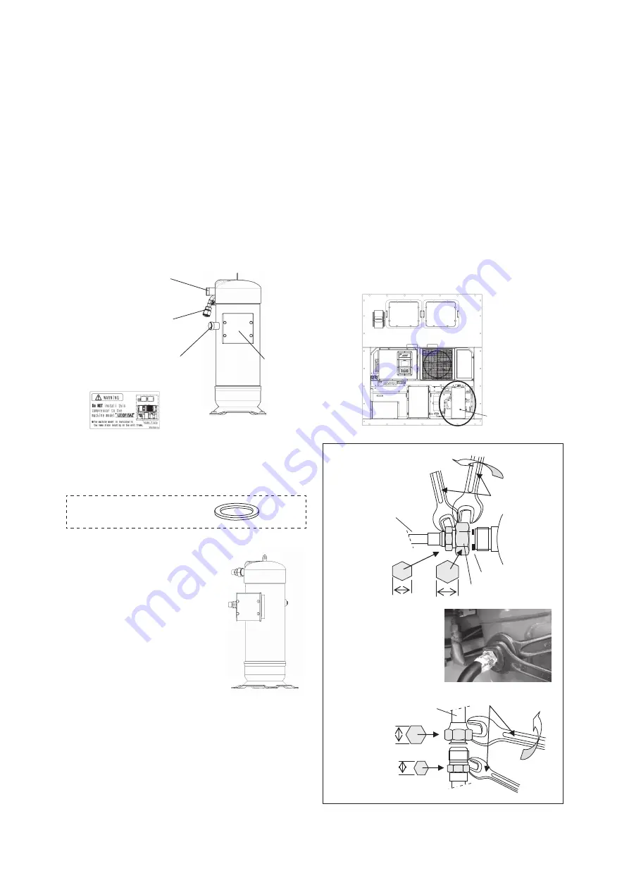
Fig. 1 Replacement compressor
*
Weight 40kg
*
Refrigerant oil DAPHNE FVC68D charged.
*
Dry nitrogen gas charged.
Suction pipe receptacle
(with a blind cap)
Discharge pipe receptacle
(with a blind cap)
Injection pipe receptacle
(with a blind cap)
Identification plate
Terminal
box
Compressor identification plate
<
Accessories
>
Packing for suction/ discharge
2 pcs.
pipe receptacles
2. Remove the blind caps from
the discharge, suction and
injection pipe receptacles.
●
Compressor removal
1. Remove the compressor cover (Fig. 2).
2. Disconnect the compressor cable from the
terminal box.
3.Disconnect three connecting pipes
(Discharge, suction and injection pipes)
Note 1. When removing pipes, use two wrenches
so as not to damage the pipes (Figs. 3 & 4).
Note 2. After disconnecting the discharge and
suction pipes, also remove the packing
(Fig. 3).
4. Remove the one bolt that holds the compressor
top and the four bolts that hold the compressor
base.
36
27
26
22
Fig.4
Fig.3
Suction pipe
Discharge pipe
(Lock nut connection)
Packing
Lock nut
Injection pipe
(Flare nut connection)
Two wrenches
Two wrenches
Rotate
Rotate
Hold on
Hold on
Removal of the
compressor cover
Fig.2
04章̲LX10F11B3̲TR16-02̲En.indd 4-13
04章̲LX10F11B3̲TR16-02̲En.indd 4-13
2016/02/03 16:22:06
2016/02/03 16:22:06
https://daikin-p.ru
Summary of Contents for LX10F11B3
Page 7: ...https daikin p ru ...
Page 83: ...https daikin p ru ...
Page 93: ...https daikin p ru ...
Page 121: ...https daikin p ru ...
Page 129: ...https daikin p ru ...
Page 138: ...6 9 6 6 Sequence AIR WATER COOLED AIR WATER COOLED https daikin p ru ...
Page 139: ...6 10 Stereoscopic wiring diagram AIR WATER COOLED https daikin p ru ...

