4-17
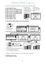
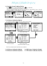
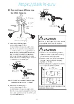
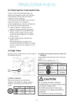
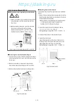
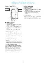
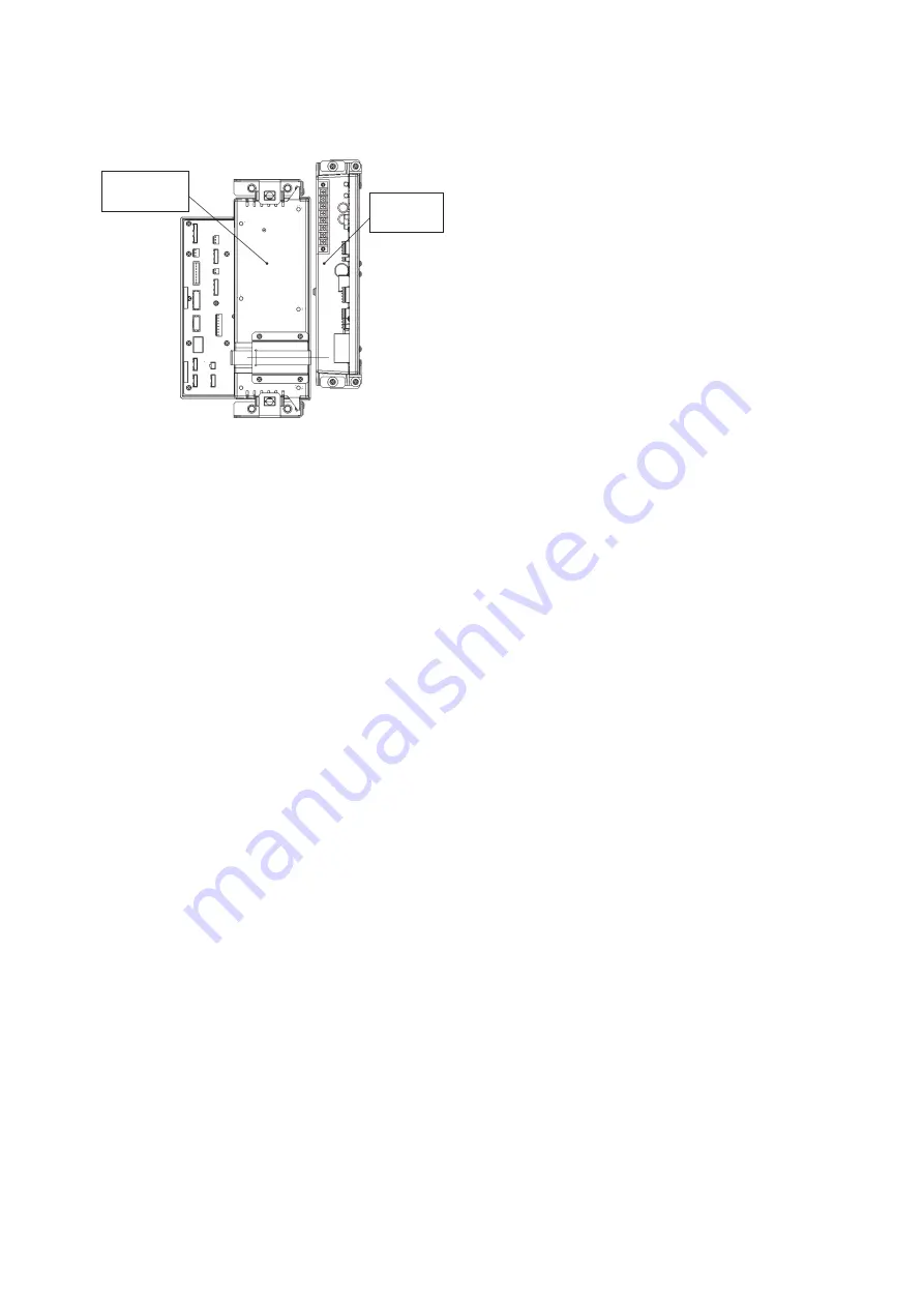
4.8.4 CPU Board (EC1)
I/O board
(EC2)
CPU board
(EC1)
●
Replacement procedure
1. Removing CPU board
1) Disconnect the cable that connects to CPU
board from the connector.
2) Remove the mounting bolts on the top and
bottom of CPU board and pull the board
forward.
3) Disconnect wake-up battery connection.
2. Mounting CPU board
Reverse the above procedure to mount the
wake-up battery, connect the cable and mount
CPU board using two bolts.
Make sure all connector are connected correctly.
3. Uploading the latest software
After mounting CPU board, upload the latest
software.
*
Download the latest software from the Daikin's
web site or request it at Daikin Service Office.
4. Necessity of configuration setting
Case 1. When using CPU board from Daikin
spare part, configuration setting is not required.
The configuration setting is not selected on
spare part CPU board but the configuration
setting values are automatically transmitted from
operation board (EC3) when power is ON.
4.8.5 I/O Board (EC2)
●
Replacement procedure
1. Removing I/O board
1) Remove the cable that connects to I/O board
from the connector.
2) Remove the mounting bolts on the top and
bottom of I/O board and pull the board
forward.
2. Mounting I/O board
Reverse the above procedure to install I/O board
using two bolts and connect the cable.
Make sure all connector are connected correctly.
04章̲LX10F11B3̲TR16-02̲En.indd 4-17
04章̲LX10F11B3̲TR16-02̲En.indd 4-17
2016/02/03 16:22:10
2016/02/03 16:22:10
https://daikin-p.ru
Summary of Contents for LX10F11B3
Page 7: ...https daikin p ru ...
Page 83: ...https daikin p ru ...
Page 93: ...https daikin p ru ...
Page 121: ...https daikin p ru ...
Page 129: ...https daikin p ru ...
Page 138: ...6 9 6 6 Sequence AIR WATER COOLED AIR WATER COOLED https daikin p ru ...
Page 139: ...6 10 Stereoscopic wiring diagram AIR WATER COOLED https daikin p ru ...

