4-22
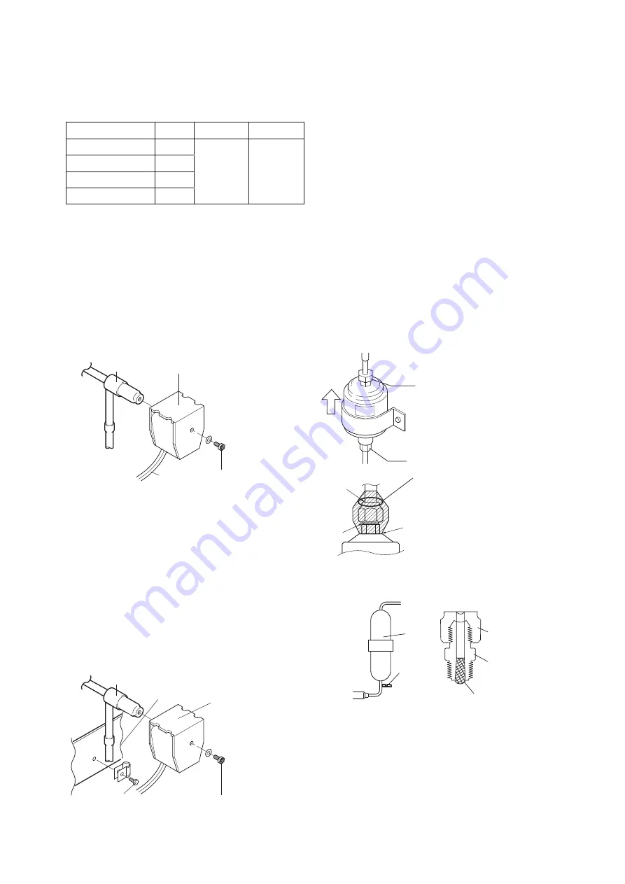
4.8.12 Solenoid Valve
4 Solenoid Valves using in this unit use a common
coil and body.
Name
Symbol
Body
Coil
Liquid solenoid Valve
LSV
VPV-
803DQ
NEV-
MOAB518C
Economizer solenoid Valve ESV
Hot gas solenoid Valve HSV
Reheat coil solenoid Valve
RSV
(1) Replacing the coil
①
Remove the lead wire connector from the inside
of the control box, and cut and recover the cable
band.
②
Remove the hexagonal head bolt on the top of
the coil and remove the coil.
③
Replace the coil with a new one and restore
the hexagonal head bolt, the cable band and
connector on the original position.
When reassembling the coil, the tightening
torque should be 1.2 N
・
m (12.2 kg
・
cm).
②
Hexagon head bolt
①
Lead wire
④
Valve body
③
Coil
(2) Replacing the valve body
①
Remove the hexagonal head bolt on the top of
the coil remove the coil.
②
Remove the hexagonal head bolt of the mounting
plate, and cut the two pipes at the side of the
valve body.
Disconnect the remaining pipes at the brazed
joint sections.
③
Solder in new valve body while keeping the
temperature of the valve body below 120
℃
(248 F) by cooling.
④
Install the coil and the hexagonal head bolt of
the mounting plate and the connector into their
original position.
⑤
Hexagon head bolt for fixing plate
①
Hexagon head bolt
②
Coil
③
Valve body
④
mounting plate
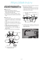
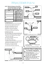
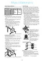
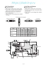
4.8.13 Dryer
The dryer absorbs moisture from the refrigerant.
It also works as a filter to remove particles in the
refrigerant system. Replace the dryer if it does not
absorb moisture, is blocked, or if the system has
been opened to the atmosphere. When installing the
new dryer, follow the arrow and do not make any
mistake about the installation direction of the dryer.
(1) Replacement procedure
①
Conduct the automatic pumpdown to collect
the refrigerant in the liquid receiver.
Refer to paragraph 4.2 for the automatic pumpdown.
②
Then, quickly replace the dryer with a new one
after loosening the flare nuts on the inlet and
outlet side of the dryer.
③
After completing of the replacement of the dryer,
be sure to conduct refrigerant leakage test to
confirm that no refrigerant leakage is occurring.
④
Check on the green color of the sight glass after
system start up.
⑤
Apply silicon sealant to the dryer body including
the flare nuts on the inlet and outlet sides.
Outlet
flare
nut
Inlet
flare
nut
Fully apply silicon sealant to
the dryer body including the
flare nuts on the inlet and
outlet sides.
When put under low
temperature and pressure by
some operation conditions,
①
and
②
might have the threads
damaged by frozen dew
drops.
③
may become rusty as a
result of coating peel-off at
work using a spanner.
①
②
③
4.8.14 Fusible Plug
Receiver
Fusible plug
①
Cap
②
Body
③
Fusible plug
●
Replacement of fusible plug
Refrigerant system pressure rise abnormally
fusible plug will release pressure.
If the fusible plug is activated, the fusible alloy
③
melts and refrigerant blow out (Melting point:
95
℃
to 100
℃
).
For replacement,
①
-
③
shall be replaced.
04章̲LX10F11B3̲TR16-02̲En.indd 4-22
04章̲LX10F11B3̲TR16-02̲En.indd 4-22
2016/02/03 16:22:14
2016/02/03 16:22:14
https://daikin-p.ru
Summary of Contents for LX10F11B3
Page 7: ...https daikin p ru ...
Page 83: ...https daikin p ru ...
Page 93: ...https daikin p ru ...
Page 121: ...https daikin p ru ...
Page 129: ...https daikin p ru ...
Page 138: ...6 9 6 6 Sequence AIR WATER COOLED AIR WATER COOLED https daikin p ru ...
Page 139: ...6 10 Stereoscopic wiring diagram AIR WATER COOLED https daikin p ru ...

