1-16
1.4.6 Common Control
●
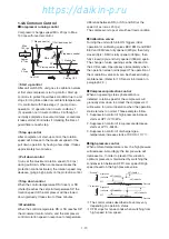
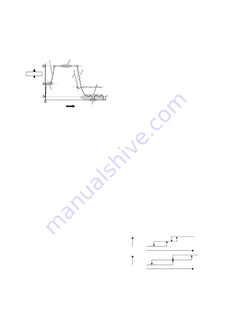
Compressor running control
Compressor changes speed Min. 20 rps to Max.
130 rps with inverter control.
①
Start up control
③
Pull down control
⑤
Modulation
Compressor
Time
Max.
130 rps
Min.
20 rps
②
Step up control
④
Step down control
Cooling OFF
SP
RS or SS
Unit ON
Approx.
67 rps
①
Start up control
After unit switch ON, unit goes to calibration valves
at first and compressor start up control. Start up
control is to protect liquid back condition due to unit
stops for long time under low ambient temperature.
It is controlled with three steps: (1) pump down
operation, (2) operation not in wet conditions 1,
(3) operation not in wet conditions 2. Although it
normally completes in several minutes, sometimes
it takes almost 20 minutes if totalizing the time of
guard timer at each step.
②
Step up control
After completion of start-up control, the rotation
speed will increase to the maximum speed of the
pull down operation by having a few steps. It takes
approximately two minutes.
③
Pull down control
It runs at the maximum rotation speed (130 rps)
during pull down. When some cause makes the
protection control activated, the rotation speed may
decrease, giving a high priority on the protection control.
④
Step down control
When the control temperature RS (frozen) or SS
(chilled) reaches the setpoint temperature SP, the
rotation speed of the compressor will be slowed
down gradually. It takes two to three minutes.
⑤
Modulation
When the control temperature RS or SS reaches SP,
the modulated control starts, and the compressor
controls rotation speed in response to temperature
difference between RS (or SS) and SP. (at the
speed of as low as 20 rps)
The compressor stops at small heat load condition.
●
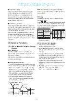
Calibration valves
Turning the unit switch into ON triggers initial
operation for calibrating valves EEV, EMV, and DMV.
EEV and EMV are fully opened (420pls) then fully
closed (0pls). DMV is fully opened (760pls), then
fully closed (0pls) and fully opened (760pls) again.
The change of valve opening can be checked on
the LCD screen. Operate keys immediately when
the operation screen is displayed. The operation of
the modulation valve coils can be checked during
maintenance. (Refer to
※
3 Sensor information in
paragraph 2.3.)
●
Compressor protection control
When an operating status phenomenon is
detected, rotation speed of the compressor will
gradually slow down to protect the compressor. It
will resume to normal operation when the operation
status returns to normal. Three examples follow.
1. Suppression control of high-pressure increase
starts at HPT
≧
2110kPa.
2. Suppression control of low-pressure decrease
starts at LPT
≦
-50kPa.
3. Suppression control of discharged-gas-
temperature increase starts at DCHS
≧
117
℃
.
●
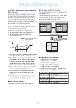
High pressure control
When ambient temperature is low, the high pressure
will decrease. Accordingly, the low pressure will
decrease too. In order to prevent this situation,
optimum pressure is maintained by switching the
condenser fan between OFF
⇔
Low speed
⇔
High
speed based on the high pressure value.
High Speed
Low Speed
OFF
HPT<800kPa
HPT>800kPa
HPT>1000kPa
HPT<600kPa
<
In operation
>
<
Startup
>
High Speed
Low Speed
OFF
HPT<500kPa
HPT>400kPa
HPT>600kPa
HPT<300kPa
Pressure
Pressure
Speed
Speed
*
The control values described above may vary
depending on operation status.
*
CFM stops for ten seconds when switching from
high speed to low speed.
01章̲LX10F11B3̲TR16-02̲En.indd 1-16
01章̲LX10F11B3̲TR16-02̲En.indd 1-16
2016/02/02 9:09:36
2016/02/02 9:09:36
https://daikin-p.ru
Summary of Contents for LX10F11B3
Page 7: ...https daikin p ru ...
Page 83: ...https daikin p ru ...
Page 93: ...https daikin p ru ...
Page 121: ...https daikin p ru ...
Page 129: ...https daikin p ru ...
Page 138: ...6 9 6 6 Sequence AIR WATER COOLED AIR WATER COOLED https daikin p ru ...
Page 139: ...6 10 Stereoscopic wiring diagram AIR WATER COOLED https daikin p ru ...

